PADS-REAR BRAKE
REMOVAL
NOTE: Before proceeding, (Refer to 5 - BRAKES - WARNING) (Refer to 5 - BRAKES - CAUTION).
NOTE: If the rear brake pads are being replaced due to a howl or moan while driving in reverse, proper diagnosis and correction is essential. (Refer to 5 - BRAKES - DIAGNOSIS AND TESTING)
1. Raise and support the vehicle. (Refer to LUBRICATION & MAINTENANCE/HOISTING - STANDARD PROCEDURE)
NOTE: Perform STEP 2 through STEP 6 on each side of the vehicle to complete pad set removal.
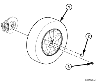
2. Remove the wheel mounting nuts (3), then the tire and wheel assembly (1).
NOTE: In some cases, it may be necessary to retract the caliper piston in its bore a small amount in order to provide sufficient clearance between the pads and the rotor to easily remove the caliper from the knuckle. This can usually be accomplished before the guide pin bolts are removed, by grasping the rear of the caliper and pulling outward working with the guide pins, thus retracting the piston. Never push on the piston directly as it may get damaged.
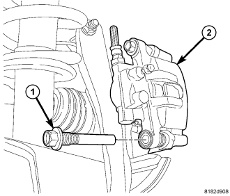
3. Remove the disc brake caliper (2) lower guide pin bolt (1).
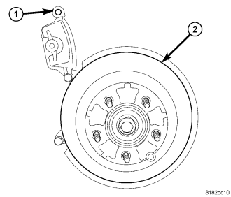
CAUTION: When moving rear brake caliper upward, use extreme care not to damage or overextend the flex hose. Damage may occur.
4. Rotate the caliper (1) upward hinging off the upper guide pin bolt. Rotate the caliper upward just enough to allow brake pad removal. Hang the caliper assembly in this position using wire or a bungee cord.
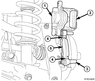
5. Remove the inboard brake pad (5) from the caliper adapter bracket (3).
6. Remove the outboard brake pad (2) from the caliper (1) by prying the brake pad retaining clip over the raised area on the caliper. Slide the brake pad off of the brake caliper.
CLEANING
WARNING: Dust and dirt accumulating on brake parts during normal use may contain asbestos fibers from production or aftermarket brake linings. Breathing excessive concentrations of asbestos fibers can cause serious bodily harm. Exercise care when servicing brake parts. Do not sand or grind brake lining unless equipment used is designed to contain the dust residue. Do not clean brake parts with compressed air or by dry brushing. Cleaning should be done by dampening the brake components with a fine mist of water, then wiping the brake components clean with a dampened cloth. Dispose of cloth and all residue containing asbestos fibers in an impermeable container with the appropriate label. Follow practices prescribed by the Occupational Safety And Health Administration (OSHA) and the Environmental Protection Agency (EPA) for the handling, processing, and disposing of dust or debris that may contain asbestos fibers.
INSPECTION
Visually inspect brake pads for uneven lining wear. Also inspect for excessive lining deterioration. Check the clearance between the tips of the wear indicators (if equipped) on the pads and the brake rotors.
If a visual inspection does not adequately determine the condition of the lining, a physical check will be necessary. To check the amount of lining wear, remove the disc brake pads from the vehicle.
Measure brake pad minimum thickness. Brake pads must be replaced when usable material on a brake pad lining measured at its thinnest point measures one millimeter (0.04 inches) or less.
NOTE: It is important to inspect both front and rear brake pads during the same inspection. Typically, front and rear brake pads wear out at the same time.
Replace both disc brake pads (inboard and outboard) at each caliper. It is also necessary to replace the pads on the opposite side of the vehicle as well as the pads failing inspection to maintain proper braking characteristics.
If the brake pad assemblies do not require replacement, be sure to reinstall the brake pads in the original position they were removed from.
INSTALLATION
NOTE: If the rear brake pads are being replaced due to a howl or moan while driving in reverse, proper diagnosis and correction is essential. (Refer to 5 - BRAKES - DIAGNOSIS AND TESTING)
NOTE: Perform STEP 1 through STEP 6 on each side of the vehicle to complete pad set installation, then proceed to STEP 7.
1. Completely retract the caliper piston back into the piston bore of the caliper. This is required to gain the necessary pad-to-rotor clearance for the caliper installation onto the steering knuckle.
NOTE: Place the brake pad with the audible wear indicator attached on the inboard side. The audible wear indicator should be positioned at the bottom when installed.
2. Slide the outboard brake pad (2) onto the caliper (1). Be sure the retaining clip is squarely seated in the depressed areas on the caliper beyond the raised retaining bead.
3. Place the inboard brake pad (5) in the abutment shims (4) clipped into the disc brake caliper adapter bracket (3) as shown (see preceding note).
CAUTION: Use care when installing the caliper onto the adapter bracket to avoid damaging the guide pin boot.
4. Rotate the disc brake caliper downward over the brake rotor and lower part of caliper adapter.
5. Install the disc brake caliper (2) lower guide pin bolt (1). Tighten the guide pin bolt to 43 N·m (32 ft. lbs.).
6. Install the tire and wheel assembly (1) (Refer to 22 - TIRES/WHEELS - INSTALLATION). Install and tighten the wheel mounting nuts (3) to 135 N·m (100 ft. lbs.).
7. Lower the vehicle.
8. Pump the brake pedal several times to ensure the vehicle has a firm brake pedal before moving the vehicle.
9. Road test the vehicle and make several stops to wear off any foreign material on the brakes and to seat the brake pads.