C211D-IGNITION RUN/START INPUT CIRCUIT HIGH
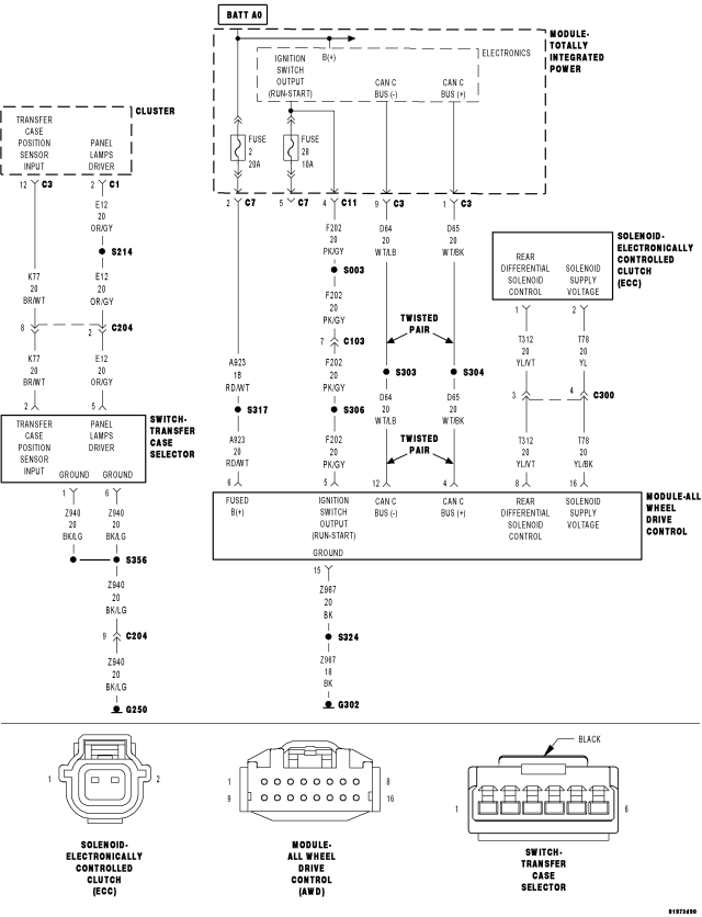
For a complete wiring diagram Refer to Section 8W.
- When Monitored:
Continuously.
- Set Condition:
The All Wheel Drive (AWD) Control Module detects that the ignition Switch circuit voltage is above 17.0 volts for more than 10 seconds.
| Possible Causes |
| (F202) IGNITION SWITCH OUTPUT (RUN/START) CIRCUIT OPEN OR HIGH RESISTANCE |
| ALL WHEEL DRIVE (AWD) CONTROL MODULE |
| TOTALLY INTEGRATED POWER MODULE (TIPM) |
Diagnostic Test
1. CHARGING SYSTEM DTCS PRESENTIgnition on, engine not running.
With the scan tool, select View DTCs in the Powertrain Control Module.
Are there any Charging System or related voltage DTCs present?
Yes
- Refer to the symptom list and perform any Charging System DTC diagnostic procedures before continuing with this test.
No
- Go to 2
2. CHECK FOR ACTIVE DTC
Ignition on, engine not running.
With the scan tool, read the active DTC.
Cycle the ignition switch from the OFF to ON position, leaving the ignition on for a minimum of 10 seconds.
With the scan tool, read the active DTC.
Does the scan tool display this DTC as active?
Yes
- Go To 3
No
- Go to 8
3. (F202) IGNITION SWITCH OUTPUT (RUN/START) CIRCUIT SHORTED TO VOLTAGE
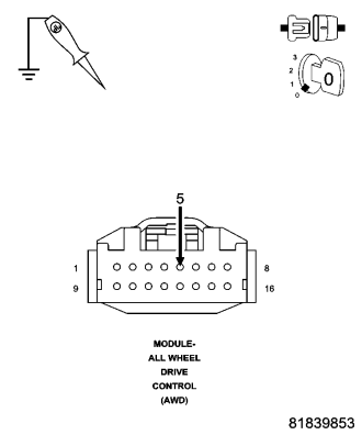
Turn the ignition off.
Disconnect the TIPM C11 harness connector.
Disconnect the AWD Control Module harness connector.
With a 12-volt test light connected to ground, check the (F202) Ignition Switch Output (RUN/START) circuit in the AWD Control Module harness connector.
NOTE: The test light must illuminate brightly. Compare the brightness to that of a direct connection to the battery.
Does the test light illuminate brightly?
Yes
- Repair the (F202) Ignition Switch Output (RUN/START) circuit for a short to voltage.
- Perform AWD Control Module VERIFICATION TEST. (Refer to 3 - DIFFERENTIAL & DRIVELINE/ELECTRONICALLY CONTROLLED CLUTCH - STANDARD PROCEDURE).
No
Go to 4
4. (F202) IGNITION SWITCH OUTPUT (RUN/START)
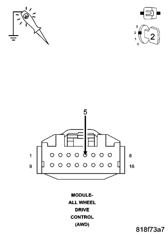
Reconnect the AWD Control Module harness connector.
Reconnect the TIPM C11 harness connector.
Ignition on, engine not running.
With a 12-volt test light connected to ground, check the (F202) Ignition Switch Output (RUN/START) circuit in the AWD Control Module harness connector.
NOTE: The test light must illuminate brightly. Compare the brightness to that of a direct connection to the battery.
Does the test light illuminate brightly?
Yes
- Go to 7
No
- Go to 5
5. CHECK THE TIPM IGNITION SWITCH OUTPUT (RUN/START)
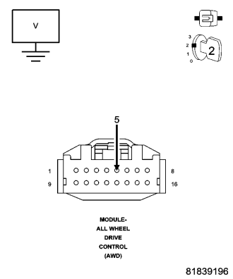
While back probing, measure the voltage of the (F202) Ignition Switch Output Run/Start circuit in the TIPM C7 harness connector.
Is the voltage below 17 volts?
Yes
- Go to 7
No
- Go to 6
6. AWD CONTROL MODULE
NOTE: Before continuing, check the AWD Module harness connector terminals for corrosion, damage, or terminal push out. Repair as necessary.
Using the schematics as a guide, inspect the wire harness and connectors.
Pay particular attention to all Power and Ground circuits.
View repair.
Repair
- Replace the AWD Control Module in accordance with the Service information.
- Perform AWD Control Module VERIFICATION TEST. (Refer to 3 - DIFFERENTIAL & DRIVELINE/ELECTRONICALLY CONTROLLED CLUTCH - STANDARD PROCEDURE).
7. TOTALLY INTEGRATED POWER MODULE
NOTE: Before continuing, check the TIPM harness connector terminals for corrosion, damage, or terminal push out. Repair as necessary.
Using the schematics as a guide, inspect the wire harness and connectors.
Pay particular attention to all Power and Ground circuits.
View repair.
Repair
- Replace the Totally Integrated Power Module in accordance with the Service Information.
- Perform AWD Control Module VERIFICATION TEST. (Refer to 3 - DIFFERENTIAL & DRIVELINE/ELECTRONICALLY CONTROLLED CLUTCH - STANDARD PROCEDURE).
8. INTERMITTENT WIRING AND CONNECTORS
The conditions necessary to set this DTC are not present at this time.
Using the schematics as a guide, inspect the wiring and connectors specific to this circuit.
Wiggle test the wiring harness and connectors while checking for shorted and open circuits.
Using the scan tool, monitor the data related to this circuit while performing the wiggle test. Look for the data to change or for the DTC to reset.
Were there any problems found?
Yes
- Repair as necessary.
- Perform AWD Control Module VERIFICATION TEST. (Refer to 3 - DIFFERENTIAL & DRIVELINE/ELECTRONICALLY CONTROLLED CLUTCH - STANDARD PROCEDURE)
No
- Test Complete.