STEERING COLUMN CONTROL MODULE
DESCRIPTION
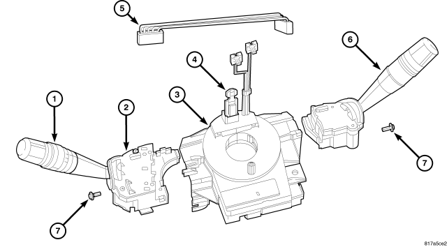
This vehicle is equipped with a Steering Control Module (SCM) that is internal to the left multi-function switch housing (2). The left (lighting) multi-function switch is located on the left side of the steering column, just below the steering wheel. This switch is the primary control for the interior and exterior lighting systems. The only visible components of the switch are the control stalk (1), control knob and control sleeve that extend through the steering column shrouds on the left side of the column. The remainder of the switch including its mounting provisions and electrical connections are concealed beneath the shrouds.
The switch housing and controls are constructed of molded black plastic. A single screw (7) through a mounting tab integral to the back of the switch housing, and a slide tab integral to the bottom of the switch housing secure the switch to the mounting bracket integral to the clockspring (3). A connector receptacle containing seven terminal pins is integral to the inboard end of the switch housing and connects the SCM through a jumper wire harness (5) directly to the right (wiper) multi-function switch (6). A second connector receptacle containing four terminal pins is integral to the back of the switch housing and connects the SCM to the vehicle electrical system through a dedicated takeout and connector of the instrument panel wire harness.
The SCM cannot be adjusted or repaired. If ineffective or damaged the entire left multi-function switch must be replaced. (Refer to 8 - ELECTRICAL/LAMPS/LIGHTING - EXTERIOR/LEFT MULTI-FUNCTION SWITCH - REMOVAL). The clockspring (with the multi-function switch mounting bracket), the left multi-function switch (with the SCM), the right multi-function switch and the jumper wire harness are each available for separate service replacement.
OPERATION
The microprocessor-based Steering Control Module (SCM) utilizes integrated circuitry to monitor hard wired analog and multiplexed inputs from both the right and left multi-function switches. In response to those inputs, the internal circuitry of the SCM allow it to transmit electronic message outputs to the ElectroMechanical Instrument Cluster (EMIC) (also known as the Cab Compartment Node/CCN) over the Local Interface Network (LIN) data bus.
In response to those inputs the internal circuitry and programming of the EMIC, which is also the LIN master module in the vehicle, allow it to control and integrate many electronic functions and features of the vehicle through both hard wired outputs and the transmission of electronic message outputs to other electronic modules in the vehicle over the Controller Area Network (CAN) data bus. (Refer to 8 - ELECTRICAL/ELECTRONIC CONTROL MODULES/COMMUNICATION - DESCRIPTION - CAN-LIN BUS).
The SCM is connected to both a fused B(+) circuit and a fused ignition switch output (run-start) circuit. It receives a path to ground at all times. These connections allow it to remain functional regardless of the ignition switch position. Any input to the SCM that controls a vehicle system function that does not require that the ignition switch be in the ON position such as turning on the lights, prompts the SCM to wake up and transmit on the LIN data bus.
The hard wired circuits between components related to the SCM may be diagnosed using conventional diagnostic tools and procedures. Refer to the appropriate wiring information. The wiring information includes wiring diagrams, proper wire and connector repair procedures, details of wire harness routing and retention, connector pin-out information and location views for the various wire harness connectors, splices and grounds.
However, conventional diagnostic methods will not prove conclusive in the diagnosis of the SCM or the electronic controls or communication between modules and other devices that provide some features of the SCM. The most reliable, efficient, and accurate means to diagnose the SCM or the electronic controls and communication related to SCM operation requires the use of a diagnostic scan tool. Refer to the appropriate diagnostic information.
REMOVAL
SCCM
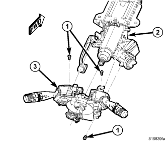
1. Place the front road wheels in the straight-ahead position.
2. Open hood.
3. Disconnect and isolate the battery negative cable.
WARNING: Wait two minutes for the airbag system reserve capacitor to discharge before beginning any airbag system or component service. Failure to do so may result in accidental airbag deployment, personal injury or death.
4. Remove steering wheel (Refer to 19 - STEERING/COLUMN/STEERING WHEEL - REMOVAL).
5. Remove upper and lower steering column shrouds to gain access to the Steering Control Module (SCCM) (Refer to 19 - STEERING/COLUMN/UPPER SHROUD - REMOVAL).
6. Lock the clockspring rotor in the center position as follows: Insert a grenade pin through the hole in the rotor at the 10 o'clock position.
7. Remove the three screws (1) to the Steering Column Control Module (SCCM) (3).
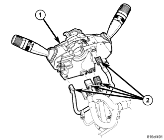
8. Disconnect the electrical connectors (2) between the SCCM (1) and the instrument panel wiring harness at the base of the SCCM and remove from column.
NOTE: If only removing the SCCM from column, there is no need to continue to next step.
DISASSEMBLY
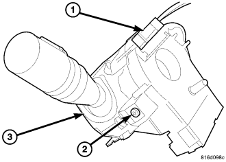
1. Remove the left multi-function switch stalk retaining screw (2).
2. Pull the left stalk out of the SCCM.
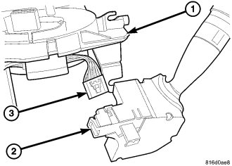
3. Disconnect the left stalk electrical connector.
4. Separate the left switch from the SCCM.
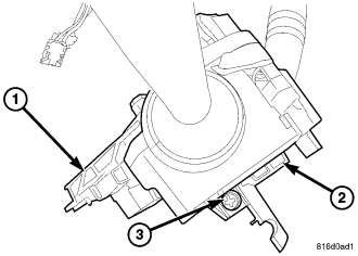
5. Remove the one right multi-function switch retaining screw.
6. Pull right switch out of SCCM.
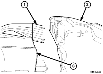
7. Disconnect the right switch electrical connector.
INSTALLATION
NOTE: If SCCM is already assembled and needs to be installed, bypass ASSEMBLY and proceed with SCCM STEP 1
ASSEMBLY
1. Connect the right stalk electrical connector.
2. Slide the right stalk into the groove and install the one retaining screw.
3. Connect the left stalk switch electrical connector.
4. Install the left stalk switch retaining screw.
SCCM
1. Position the SCCM (3) over the steering column shaft (2).
2. Install the three screws (1).
3. Connect the electrical connectors (2) to the instrument panel harness, ensure wiring is properly routed. Then check that the connectors, locking tabs are properly engaged.
4. Install steering column shrouds (Refer to 19 - STEERING/COLUMN/UPPER SHROUD - INSTALLATION). Be sure all wires are inside of shrouds.
5. Install steering wheel ensuring the flats on hub align with the clockspring (Refer to 19 - STEERING/COLUMN/STEERING WHEEL - INSTALLATION). Pull the airbag leads through the larger slot. Ensure leads do not get pinched under the steering wheel.
NOTE: There is a small wire harness in the steering wheel and it contains the horn circuits and speed control circuits.
6. Connect the speed control and horn wire connector into the clockspring.
7. Pull the grenade pin out of the clockspring.
8. Install the driver airbag, (Refer to 8 - ELECTRICAL/RESTRAINTS/DRIVER AIRBAG - INSTALLATION)
WARNING: Do not connect the battery negative cable (REFER TO 8 - ELECTRICAL/RESTRAINTS - DIAGNOSIS AND TESTING - AIRBAG SYSTEM). Personal injury or death may result if the system test is not performed first.