DRIVER AIRBAG
DESCRIPTION
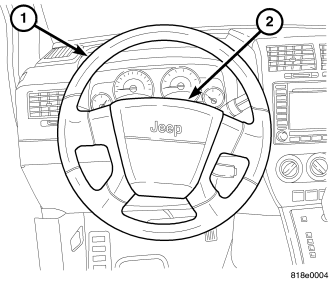
The injection molded, thermoplastic driver airbag protective trim cover (2) is the most visible part of the driver airbag. The driver airbag is located in the center of the steering wheel (1), where it is secured with two screws to the horn switch within the hub cavity of the four-spoke steering wheel. An injection molded, bright emblem with the Jeep® logo is applied to the center of the trim cover.
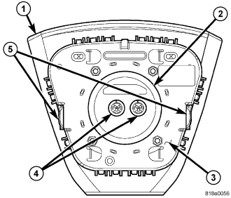
Concealed beneath the driver air bag trim cover are the folded airbag cushion, the airbag housing, the airbag inflator and the retainers that secure the inflator to the housing. The airbag cushion, housing (3), and inflator (2) are secured within an integral receptacle molded into the back of the trim cover. The four vertical walls of this receptacle have numerous small windows with blocking tabs that are engaged by numerous hook formations around the perimeter of the airbag housing. Each hook is inserted through one of the windows and the blocking tab in each window keeps the hook properly engaged with the trim cover, locking the trim cover securely into place on the airbag housing. The two mounting tabs (5) extend from the housing to secure the housing to the horn switch.
The airbag used in this vehicle is a multistage-type that complies with revised federal airbag standards to deploy with less force than those used in some prior vehicles. A radial deploying 67.3 centimeter (26.5 inch) diameter fabric airbag cushion with internal tethers is used. The airbag inflator is a dual-initiator, non-azide, pyrotechnic-type unit with four mounting studs and is secured to the stamped metal airbag housing using four flanged hex nuts. Two keyed and color-coded connector receptacles (4) on the driver airbag inflator connect the two inflator initiators to the vehicle electrical system through two yellow-jacketed, two-wire pigtail harnesses of the clockspring.
The driver airbag cannot be repaired, and must be replaced if deployed, ineffective, or in any way damaged. The driver airbag trim cover may be disassembled from the driver airbag unit, and is available for individual service replacement.
OPERATION
The multistage driver airbag is deployed by electrical signals generated by the Occupant Restraint Controller (ORC) through the driver airbag squib 1 and squib 2 circuits to the two initiators in the airbag inflator. By using two initiators, the airbag can be deployed at multiple levels of force. The force level is controlled by the ORC to suit the monitored impact conditions by providing one of several delay intervals between the electrical signals provided to the two initiators. The longer the delay between these signals, the less forcefully the airbag will deploy.
When the ORC sends the proper electrical signals to each initiator, the electrical energy generates enough heat to initiate a small pyrotechnic charge which, in turn ignites chemical pellets within the inflator. Once ignited, these chemical pellets burn rapidly and produce a large quantity of inert gas. The inflator is sealed to the back of the airbag housing and a diffuser in the inflator directs all of the inert gas into the airbag cushion, causing the cushion to inflate. As the cushion inflates, the driver airbag trim cover will split at predetermined breakout lines, then fold back out of the way. Following an airbag deployment, the airbag cushion quickly deflates by venting the inert gas towards the instrument panel through vent holes within the fabric used to construct the back (steering wheel side) panel of the airbag cushion.
Some of the chemicals used to create the inert gas may be considered hazardous while in their solid state before they are burned, but they are securely sealed within the airbag inflator. Typically, both initiators are used and all potentially hazardous chemicals are burned during an airbag deployment event. However, it is possible for only one initiator to be used during a deployment due to an airbag system fault; therefore, it is necessary to always confirm that both initiators have been used in order to avoid the improper disposal of potentially live pyrotechnic or hazardous materials. (Refer to 8 - ELECTRICAL/RESTRAINTS - STANDARD PROCEDURE - SERVICE AFTER A SUPPLEMENTAL RESTRAINT DEPLOYMENT).
The inert gas that is produced when the chemicals are burned is harmless. However, a small amount of residue from the burned chemicals may cause some temporary discomfort if it contacts the skin, eyes, or breathing passages. If skin or eye irritation is noted, rinse the affected area with plenty of cool, clean water. If breathing passages are irritated, move to another area where there is plenty of clean, fresh air to breath. If the irritation is not alleviated by these actions, contact a physician.
Proper diagnosis of the driver airbag inflator and squib circuits requires the use of a diagnostic scan tool. Refer to the appropriate diagnostic information.
REMOVAL
WARNING: To avoid serious or fatal injury, on vehicles equipped with airbags, disable the supplemental restraint system before attempting any steering wheel, steering column, airbag, occupant classification system, seat belt tensioner, impact sensor, or instrument panel component diagnosis or service. Disconnect and isolate the battery negative (ground) cable, then wait two minutes for the system capacitor to discharge before performing further diagnosis or service. This is the only sure way to disable the supplemental restraint system. Failure to take the proper precautions could result in accidental airbag deployment.
WARNING: To avoid serious or fatal injury, when removing a deployed airbag, rubber gloves, eye protection, and a long-sleeved shirt should be worn. There may be deposits on the airbag cushion and other interior surfaces. In large doses, these deposits may cause irritation to the skin and eyes.
NOTE: The following procedure is for replacement of an ineffective or damaged driver airbag. If the airbag is ineffective or damaged, but not deployed, review the recommended procedures for handling non-deployed supplemental restraints. (Refer to 8 - ELECTRICAL/RESTRAINTS - STANDARD PROCEDURE - HANDLING NON-DEPLOYED SUPPLEMENTAL RESTRAINTS). If the driver airbag has been deployed, review the recommended procedures for service after a supplemental restraint deployment before removing the airbag from the vehicle. (Refer to 8 - ELECTRICAL/RESTRAINTS - STANDARD PROCEDURE - SERVICE AFTER A SUPPLEMENTAL RESTRAINT DEPLOYMENT).
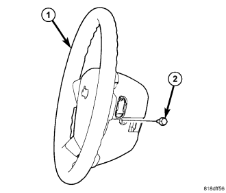
1. Disconnect and isolate the battery negative cable. Wait two minutes for the system capacitor to discharge before further service.
2. From the side of the steering wheel (1) hub trim cover, remove the two screws (2) that secure the driver airbag to the horn switch within the hub of the steering wheel.
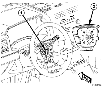
3. Pull the driver airbag (2) away from the steering wheel far enough to access the electrical connections (1) at the back of the airbag housing.
CAUTION: Do not pull on the clockspring pigtail wires or pry on the connector insulator to disengage the connector from the driver airbag inflator connector receptacle. Improper removal of these pigtail wires and their connector insulators can result in damage to the airbag circuits or the connector insulators.
4. The clockspring driver airbag pigtail wire connectors are secured by an integral lock to the airbag inflator connector receptacles, which are located on the back of the driver airbag housing. Firmly grasp and pull the lock straight out from the connector insulator, then pull the insulators straight out from the airbag inflator to disconnect them from the connector receptacles.
5. Remove the driver airbag from the steering wheel.
6. If the driver airbag has been deployed, the clockspring must be replaced. (Refer to 8 - ELECTRICAL/RESTRAINTS/CLOCKSPRING - REMOVAL).
DISASSEMBLY
WARNING: To avoid serious or fatal injury, on vehicles equipped with airbags, disable the supplemental restraint system before attempting any steering wheel, steering column, airbag, occupant classification system, seat belt tensioner, impact sensor, or instrument panel component diagnosis or service. Disconnect and isolate the battery negative (ground) cable, then wait two minutes for the system capacitor to discharge before performing further diagnosis or service. This is the only sure way to disable the supplemental restraint system. Failure to take the proper precautions could result in accidental airbag deployment.
WARNING: To avoid serious or fatal injury, service of this unit should be performed only by DaimlerChrysler-trained and authorized dealer service technicians. Failure to take the proper precautions or to follow the proper procedures could result in accidental, incomplete, or improper airbag deployment and possible occupant injuries.
WARNING: To avoid serious or fatal injury, use extreme care to prevent any foreign material from entering the driver airbag, or becoming entrapped between the driver airbag cushion and the driver airbag trim cover. Failure to observe this warning could result in occupant injuries upon airbag deployment.
WARNING: To avoid serious or fatal injury, the driver airbag trim cover must never be painted. Replacement trim covers are serviced in the original colors. Paint may change the way in which the material of the trim cover responds to an airbag deployment. Failure to observe this warning could result in occupant injuries upon airbag deployment.
NOTE: The following procedures can be used to replace the driver airbag trim cover for service. If the driver airbag is ineffective or deployed, the entire driver airbag and trim cover must be replaced as a unit.
1. Disconnect and isolate the battery negative cable. Wait two minutes for the system capacitor to discharge before further service.
2. Remove the driver airbag from the steering wheel. (Refer to 8 - ELECTRICAL/RESTRAINTS/DRIVER AIRBAG - REMOVAL).
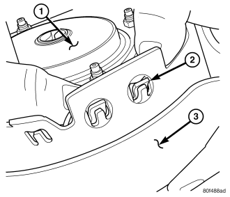
3. Place the driver airbag on a suitable work surface with the trim cover (3) facing down. If the trim cover will be reused, be certain to take the proper precautions to prevent the trim cover from receiving cosmetic damage during the following procedures.
4. Disengage each of the 16 hooks (2) of the airbag housing unit from the 16 windows in the vertical walls of the trim cover, one wall at a time. To disengage the hooks, use hand pressure to push the adjacent edge of the airbag inflator (1) or housing firmly and evenly downward into the trim cover receptacle, while at the same time pulling outward on the upper edge of the receptacle wall.
5. With all of the hooks disengaged, lift the housing, inflator and cushion as a unit from the receptacle on the back of the driver airbag trim cover.
ASSEMBLY
WARNING: To avoid serious or fatal injury, on vehicles equipped with airbags, disable the supplemental restraint system before attempting any steering wheel, steering column, airbag, occupant classification system, seat belt tensioner, impact sensor, or instrument panel component diagnosis or service. Disconnect and isolate the battery negative (ground) cable, then wait two minutes for the system capacitor to discharge before performing further diagnosis or service. This is the only sure way to disable the supplemental restraint system. Failure to take the proper precautions could result in accidental airbag deployment.
WARNING: To avoid serious or fatal injury, service of this unit should be performed only by DaimlerChrysler-trained and authorized dealer service technicians. Failure to take the proper precautions or to follow the proper procedures could result in accidental, incomplete, or improper airbag deployment and possible occupant injuries.
WARNING: To avoid serious or fatal injury, use extreme care to prevent any foreign material from entering the driver airbag, or becoming entrapped between the driver airbag cushion and the driver airbag trim cover. Failure to observe this warning could result in occupant injuries upon airbag deployment.
WARNING: To avoid serious or fatal injury, the driver airbag trim cover must never be painted. Replacement trim covers are serviced in the original colors. Paint may change the way in which the material of the trim cover responds to an airbag deployment. Failure to observe this warning could result in occupant injuries upon airbag deployment.
NOTE: The following procedures can be used to replace the driver airbag trim cover for service. If the driver airbag is ineffective or deployed, the entire driver airbag and trim cover must be replaced as a unit.
1. Place the driver airbag trim cover (3) on a suitable work surface with the airbag receptacle facing up. Be certain to take the proper precautions to prevent the trim cover from receiving cosmetic damage during the following procedures.
2. Carefully position the driver airbag housing and inflator unit (1) into the trim cover receptacle.
3. Work around the perimeter of the unit engaging each of the 16 hooks (2) on the driver airbag housing through the 16 windows in the walls of the trim cover receptacle.
4. After the driver airbag has been assembled, try pulling the trim cover and the airbag housing away from each other. This action will fully seat the edges of the trim cover windows into the cradles of the housing hooks.
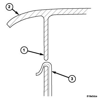
5. Before reinstalling the airbag onto the steering wheel, check that the blocking tab (1) in each of the trim cover (2) windows is oriented over the airbag housing hook (3) as shown.
6. Reinstall the driver airbag onto the steering wheel. (Refer to 8 - ELECTRICAL/RESTRAINTS/DRIVER AIRBAG - INSTALLATION).
INSTALLATION
WARNING: To avoid serious or fatal injury, on vehicles equipped with airbags, disable the supplemental restraint system before attempting any steering wheel, steering column, airbag, occupant classification system, seat belt tensioner, impact sensor, or instrument panel component diagnosis or service. Disconnect and isolate the battery negative (ground) cable, then wait two minutes for the system capacitor to discharge before performing further diagnosis or service. This is the only sure way to disable the supplemental restraint system. Failure to take the proper precautions could result in accidental airbag deployment.
WARNING: To avoid serious or fatal injury, use extreme care to prevent any foreign material from entering the driver airbag, or becoming entrapped between the driver airbag cushion and the driver airbag trim cover. Failure to observe this warning could result in occupant injuries upon airbag deployment.
WARNING: To avoid serious or fatal injury, the driver airbag trim cover must never be painted. Replacement airbags are serviced with trim covers in the original colors. Paint may change the way in which the material of the trim cover responds to an airbag deployment. Failure to observe this warning could result in occupant injuries upon airbag deployment.
NOTE: The following procedure is for replacement of an ineffective or damaged driver airbag. If the airbag is ineffective or damaged, but not deployed, review the recommended procedures for handling non-deployed supplemental restraints. (Refer to 8 - ELECTRICAL/RESTRAINTS - STANDARD PROCEDURE - HANDLING NON-DEPLOYED SUPPLEMENTAL RESTRAINTS). If the driver airbag has been deployed, review the recommended procedures for service after a supplemental restraint deployment before removing the airbag from the vehicle. (Refer to 8 - ELECTRICAL/RESTRAINTS - STANDARD PROCEDURE - SERVICE AFTER A SUPPLEMENTAL RESTRAINT DEPLOYMENT).
1. Position the driver airbag (2) close enough to the steering wheel to reconnect the electrical connections on the back of the airbag housing.
2. When installing the driver airbag, reconnect the two clockspring driver airbag pigtail wire connectors (1) to the airbag inflator connector receptacles by pressing straight in on the connectors, then pushing the locks straight into the connectors. Be certain to engage each keyed and color-coded connector to the matching connector receptacle.
3. Carefully position the driver airbag in the steering wheel (1). Be certain that the clockspring pigtail wires are not pinched between the driver airbag and the horn switch or the steering wheel armature.
4. From the side of the steering wheel hub trim cover, install and tighten the two screws (2) that secure the driver airbag to the horn switch. Tighten the screws to 13 N·m (115 in. lbs.).
5. Do not reconnect the battery negative cable at this time. The supplemental restraint system verification test procedure should be performed following service of any supplemental restraint system component. (Refer to 8 - ELECTRICAL/RESTRAINTS - STANDARD PROCEDURE - VERIFICATION TEST).