BAR-STABILIZER
REMOVAL
NOTE: Before proceeding, (Refer to 2 - SUSPENSION/FRONT - WARNING).
1. Raise and support the vehicle. (Refer to LUBRICATION & MAINTENANCE/HOISTING - STANDARD PROCEDURE)
2. If equipped, remove the engine belly pan. (Refer to 23 - BODY/EXTERIOR/BELLY PAN - REMOVAL)
3. Remove the rear engine mount. (Refer to 9 - ENGINE/ENGINE MOUNTING/REAR MOUNT - REMOVAL)
4. Remove the front engine mount through-bolt.
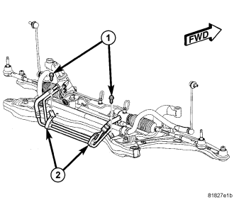
5. Remove the fasteners (1) securing the power steering hose routing clamps (2) to the crossmember.
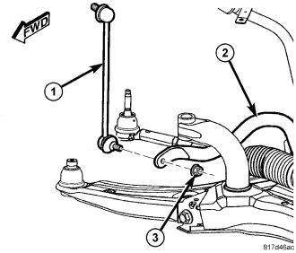
6. At each end of the stabilizer bar, while holding the stabilizer bar link (1) lower stud stationary, remove the nut (3) securing the link to the stabilizer bar (2).
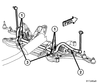
7. Remove the screws (1) securing the stabilizer bushing retainers (3) to the crossmember.
8. Remove the two stabilizer bushing retainers.
9. Utilizing the slit cut into the cushions (bushings), remove the two cushions from the stabilizer bar.
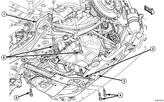
NOTE: Before removing the front suspension crossmember from the vehicle, the location of the crossmember must be marked on the body of the vehicle. Do this so the crossmember can be relocated, upon reinstallation, against the body of vehicle in the same location as before removal. If the front suspension crossmember is not reinstalled in exactly the same location as before removal, the preset front wheel alignment settings (caster and camber) may be lost.
10. Mark the location of the front crossmember on the body near each mounting bolt.
11. Support the crossmember with a transmission jack.
12. Remove the four mounting bolts (6) securing the front crossmember (1) to the body.
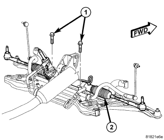
13. Remove the two bolts (1) securing the steering gear (2) to the crossmember.
14. Support the steering gear using a bungee cord or other to keep the steering gear from lowering when the crossmember is lowered.
15. Slowly lower the crossmember until there is enough space present to remove the stabilizer bar between the rear of the crossmember and the body. Due to the fact that the fore-and-aft crossmember is still attached, do not lower crossmember any more than necessary to remove the stabilizer bar.
16. Remove the stabilizer bar out over rear of crossmember.
INSTALLATION
NOTE: Before stabilizer bar installation, inspect the cushions and links for excessive wear, cracks, damage and distortion. Replace any pieces failing inspection.
NOTE: Before installing the stabilizer bar, make sure the bar is not upsidedown. The stabilizer bar (1) must be installed so that when in mounted position, the ends of the bar curve over the top of the steering gear before attaching to the links.
1. Install the stabilizer bar, link ends first, from the rear over top of the crossmember. Curve the ends of the bar over the steering gear.
2. Slowly raise the crossmember (1) into mounted position using the transmission jack matching the crossmember to the marked locations on the body made during removal.
3. Install the four mounting bolts (6) securing the front crossmember (1) to the body. Tighten the crossmember mounting bolts to 190 N·m (140 ft. lbs.).
4. Remove the transmission jack.
5. Remove the bungee cord or other supporting the steering gear (2).
6. Install the two bolts (1) securing the steering gear (2) to the crossmember. Tighten the steering gear mounting bolts to 70 N·m (52 ft. lbs.).
7. Install the two cushions (bushings) on the stabilizer bar utilizing the slit cut into the cushion sides.
8. Install the two stabilizer bushing retainers (3) over the cushions.
9. Install the screws (1) securing the stabilizer bushing retainers (3) to the crossmember. Tighten all four stabilizer bar cushion retainer screws to 30 N·m (22 ft. lbs.).
10. Attach the stabilizer bar link (1) at each end of the stabilizer bar (2). At each link, install and tighten the nut (3) while holding the stabilizer bar link lower stud stationary. Tighten the nuts to 58 N·m (43 ft. lbs.).
11. Position the power steering hose routing clamps (2) on the crossmember. Install the fasteners. Tighten the screw to 8 N·m (71 in. lbs.).
12. Install the rear engine mount. (Refer to 9 - ENGINE/ENGINE MOUNTING/REAR MOUNT - REMOVAL)
13. If equipped, install the engine belly pan. (Refer to 23 - BODY/EXTERIOR/BELLY PAN - REMOVAL)
14. Lower the vehicle.
15. Perform wheel alignment as necessary paying special attention to front camber and caster. The crossmember may need to be shifted on its mounts slightly to gain preferred setting. (Refer to 2 - SUSPENSION/WHEEL ALIGNMENT - STANDARD PROCEDURE)