KNUCKLE
DESCRIPTION
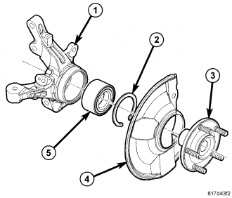
The knuckle (1) is a single casting with legs machined for attachment to the front strut assembly on the top, lower control arm ball joint on the bottom, and steering linkage on the trailing end. The knuckle also has two machined, drilled and tapped legs on the leading end casting to support and align the front disc brake caliper adapter.
The knuckle supports the wheel bearing (5) and hub (3). The hub is pressed into a sealed-for-life wheel bearing that is pressed into the knuckle. A snap ring also holds the bearing in place. A shield is pressed onto the knuckle behind the hub.
REMOVAL
NOTE: Before proceeding, review all Warnings and Cautions. (Refer to 2 - SUSPENSION/FRONT - WARNING)
1. Raise and support the vehicle. (Refer to LUBRICATION & MAINTENANCE/HOISTING - STANDARD PROCEDURE)
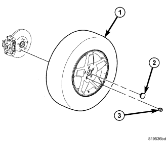
2. Remove the wheel mounting nuts (3), then the tire and wheel assembly (1).
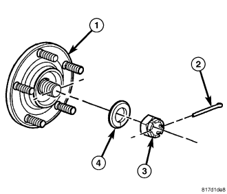
3. Remove the cotter pin (2) from the hub nut (3).
4. While a helper applies the brakes to keep the hub (1) from rotating, remove the hub nut (3) and washer (4) from the axle half shaft.
5. Access and remove the front brake rotor. (Refer to 5 - BRAKES/HYDRAULIC/MECHANICAL/ROTOR - REMOVAL)
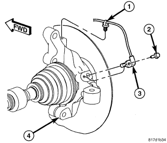
6. Remove the routing clip (1) securing wheel speed sensor cable to the knuckle (4).
7. Remove the screw (2) fastening the wheel speed sensor head (3) to the knuckle (4). Pull the sensor head out of the knuckle.
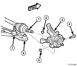
8. Remove the nut (2) attaching the outer tie rod (7) to the knuckle (3). To do this, hold the tie rod end stud with a wrench while loosening and removing the nut with a standard wrench or crowfoot wrench.
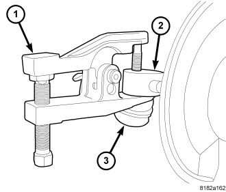
9. Release the outer tie rod end (3) from the knuckle (2) using Remover (1), Special Tool 9360.
10. Remove the outer tie rod from the knuckle.
11. Remove the nut (5) and pinch bolt (4) clamping the ball joint stud (6) to the knuckle (3).
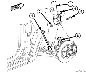
CAUTION: The strut assembly-to-knuckle attaching bolts (5) are serrated and must not be turned during removal. Proper removal is required. Refer to the following steps for the correct method.
12. While holding the bolt heads stationary, remove the two nuts (2) from the bolts (5) attaching the strut (3) to the knuckle (6).
13. Remove the two bolts (5) attaching the strut (3) to the knuckle (6) using a pin punch.
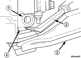
CAUTION: Use care when separating the ball joint stud (4) from the knuckle (1), so the ball joint seal does not get cut.
14. Using an appropriate prying tool (2), separate the ball joint stud (4) from the knuckle (1) by prying down on lower control arm (3) and up against the ball joint boss on the knuckle.
NOTE: Do not allow the half shaft (1) to hang by the inner C/V joint; it must be supported to keep the joint from separating during this operation.
15. Pull the knuckle (3) off the half shaft (1) outer C/V joint splines and remove the knuckle from the vehicle.
INSTALLATION
1. Slide the hub of the knuckle (3) onto the splines of the halfshaft outer C/V joint (1).
2. Install the knuckle (3) onto the ball joint (6) stud aligning the bolt hole in the knuckle boss with the groove formed into the side of the ball joint stud.
3. Install a NEW ball joint stud pinch bolt (4) and nut (5). Tighten the nut to 82 N·m (60 ft. lbs.).
CAUTION: The strut assembly-to-knuckle attaching bolts (2) are serrated and must not be turned during installation. Install the nuts while holding the bolts stationary in the steering knuckle. Refer to the following step.
4. Position the lower end of the strut assembly (3) in line with the upper end of the knuckle (6), aligning the mounting holes. Install the two mounting bolts (5).
5. Install the nuts (2) on the two bolts (5). While holding the bolts in place, tighten the nuts to 84 N·m (62 ft. lbs.).
6. Install the outer tie rod (7) ball stud into the hole in the knuckle (3) arm. Start the tie rod end-to-knuckle nut (2) onto the stud. While holding the tie rod end stud with a wrench, tighten the nut with a wrench or crowfoot wrench to 132 N·m (97 ft. lbs.).
7. Install the wheel speed sensor head (3) into the knuckle (4). Install the mounting screw (2) and tighten it to 12 N·m (106 in. lbs.).
8. Install the routing clip (1) securing the wheel speed sensor cable to the knuckle (4).
9. Install the brake rotor, disc brake caliper and adapter. (Refer to 5 - BRAKES/HYDRAULIC/MECHANICAL/ROTOR - INSTALLATION)
10. Clean all foreign matter from the threads of the halfshaft outer C/V joint.
11. Install the washer (4) and hub nut (3) on the end of the halfshaft and snug it.
12. While a helper applies the brakes to keep the hub (1) from rotating, tighten the hub nut (3) to 245 N·m (181 ft. lbs.).
13. Insert the cotter pin (2) through the notches in the nut and the hole in halfshaft. If the notches in the nut do not line up with the hole in the halfshaft, continue to tighten the nut until they do. Do not loosen the nut.
14. Wrap the cotter pin (2) ends tightly around the lock nut.
15. Install the tire and wheel assembly (1) (Refer to 22 - TIRES/WHEELS - INSTALLATION). Install and tighten the wheel mounting nuts (3) to 135 N·m (100 ft. lbs.).
16. Lower the vehicle.
NOTE: If the original knuckle is being reinstalled, wheel alignment may not be necessary due to Net-Build design.
17. Perform wheel alignment as necessary. (Refer to 2 - SUSPENSION/WHEEL ALIGNMENT - STANDARD PROCEDURE)