STRUT ASSEMBLY
DESCRIPTION
A Macpherson type design strut assembly is used in place of the front suspension upper control arm and upper ball joint. The bottom of the strut mounts directly to the steering knuckle using two attaching bolts and nuts going through the strut clevis bracket and knuckle. The top of the strut mounts directly to the strut tower of the vehicle using the three threaded studs on the strut assemblies upper mount.
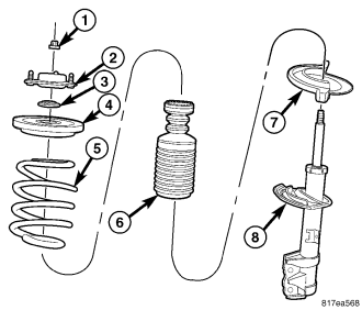
The strut assembly includes the following components:
- Upper mount (rubber isolated) (2)
- Bearing (3)
- Upper spring seat and isolator (4)
- Coil spring (5)
- Dust shield and jounce bumper (6)
- Lower spring isolator (7)
- Strut (damper) (8)
Each component is serviced by removing the strut assembly from the vehicle and disassembling it.
Coil springs are rated separately for each corner or side of the vehicle depending on optional equipment and type of vehicle service. If a coil spring requires replacement, be sure that it is replaced with a spring meeting the correct load rating for the vehicle and its specific options.
OPERATION
The strut assembly cushions the ride of the vehicle, controlling vibration, jounce and rebound of the suspension.
The coil spring controls ride quality and maintains proper ride height.
The spring isolators isolate the coil spring at the top and bottom from coming into metal-to-metal contact with the upper mounting seat and the strut.
The jounce bumper limits suspension travel and metal-to-metal contact under full jounce condition.
The strut dampens jounce and rebound motions of the coil spring and suspension.
REMOVAL
NOTE: Before proceeding, (Refer to 2 - SUSPENSION/FRONT - WARNING).
1. Raise and support the vehicle. (Refer to LUBRICATION & MAINTENANCE/HOISTING - STANDARD PROCEDURE)
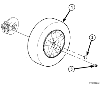
2. Remove the wheel mounting nuts (3), then the tire and wheel assembly (1).
NOTE: If both strut assemblies are to be removed, mark the strut assemblies right or left and keep the parts separated to avoid mix-up. Not all parts of the strut assembly are interchangeable side-to-side.
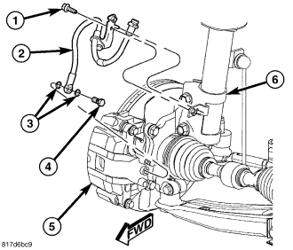
3. Remove the screw (1) securing the flex hose (2) routing bracket to the strut (6).
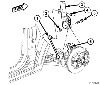
4. While holding the stabilizer bar link (1) stud stationary, remove the nut (4) securing the link to the strut (3).
CAUTION: The strut assembly-to-knuckle attaching bolts (5) are serrated and must not be turned during removal. Hold the bolts stationary in the knuckle while removing the nuts, then tap the bolts out using a pin punch.
5. While holding the bolt heads stationary, remove the two nuts (2) from the bolts (5) attaching the strut (3) to the knuckle (6).
6. Remove the two bolts (5) attaching the strut (3) to the knuckle (6) using a pin punch.
7. Lower the vehicle just enough to open the hood without allowing the tires to touch the floor.
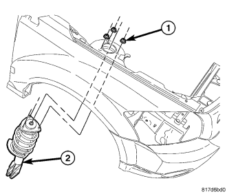
8. Remove the three nuts (1) attaching the strut assembly (2) upper mount to the strut tower.
9. Remove the strut assembly (2) from the vehicle.
10. For disassembly, (Refer to 2 - SUSPENSION/FRONT/STRUT - DISASSEMBLY).
DISASSEMBLY
NOTE: The strut assembly must be removed from the vehicle for it to be disassembled and assembled. (Refer to 2 - SUSPENSION/FRONT/STRUT - REMOVAL)
For the disassembly and assembly of the strut assembly, use strut spring compressor, Pentastar Service Equipment (PSE) tool W-7200, or equivalent, to compress the coil spring. Follow the manufacturer's instructions closely.
WARNING: Do not remove the strut rod nut before the coil spring is properly compressed. The coil spring is held under pressure. The coil spring must be compressed, removing spring tension from the upper mount and bearing, before the strut rod nut is removed.
1. If both struts are being serviced at the same time, mark both the coil spring and strut assembly according to which side of the vehicle the strut is being removed from.
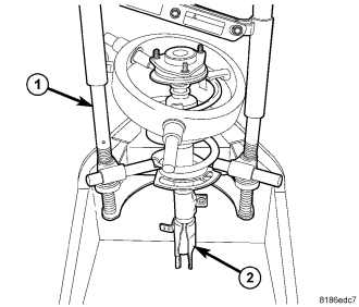
2. Position the strut assembly (2) in the strut coil spring compressor (1) following the manufacturers instructions and set the lower and upper hooks of the compressor on the coil spring. Position the strut clevis bracket (4) straight outward, away from the compressor.
3. Compress the coil spring until all coil spring tension is removed from the upper mount and bearing.
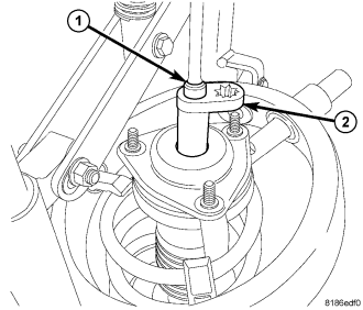
CAUTION: Never use impact or high speed tools to remove the strut rod nut. Damage to the strut internal bearings can occur.
4. Once the spring is sufficiently compressed, install Strut Nut Wrench (2), Special Tool 9362, on the strut rod nut. Next, install Strut Shaft Socket (1), Special Tool 9894, on the end of the strut rod. While holding the strut rod from turning, remove the nut using the strut nut wrench.
5. Remove the clamp (if installed) from the bottom of the coil spring and remove the strut (damper) (8) out through the bottom of the coil spring. the dust shield and jounce bumper will come out with the strut.
6. Remove the lower isolator (7) from the strut seat.
7. Slide the dust shield and jounce bumper (6) from the strut rod.
8. Remove the upper mount (2) and bearing (3) from the top of the upper spring seat and isolator (4).
9. Remove the upper spring seat and isolator (4) from the top of the coil spring (5).
10. Remove the lower spring isolator (2) from the lower spring seat on the strut (1).
NOTE: If the coil spring needs to be serviced, proceed with the next step, otherwise, proceed with STEP 12.
11. Release the tension from the coil spring by backing off the compressor drive completely. Push back the compressor hooks and remove the coil spring.
12. Inspect the strut assembly components for the following and replace as necessary:
- Inspect the strut (damper) (8) for shaft binding over the full stroke of the shaft.
- Inspect the jounce bumper (with dust shield) (6) for cracks and signs of deterioration.
- Check the upper mount (2) for cracks and distortion and its retaining studs for any sign of damage.
- Check the bearing (3) for any binding.
- Check the upper spring seat and isolator (4) for cracks and distortion.
- Inspect the upper and lower spring isolators (7) for material deterioration and distortion.
- Inspect the coil spring (5) for any sign of damage to the coating.
NOTE: For reassembly, (Refer to 2 - SUSPENSION/FRONT/STRUT - ASSEMBLY).
ASSEMBLY
NOTE: If the coil spring has been removed from the spring compressor, proceed with the next step, otherwise, proceed with STEP 3.
1. Place the coil spring in the spring compressor following the manufacturers instructions. Before compressing the spring, rotate the spring so the end of the bottom coil is at approximately the 9 o'clock position as viewed above (or to where the spring was when removed from the compressor). This action will allow the strut (damper) clevis bracket to be positioned outward, away from the compressor once installed.
2. Slowly compress the coil spring until enough room is available for strut assembly reassembly.
3. Install the upper spring seat and isolator (4) on top of the coil spring (5).
4. Install the bearing (3) and upper mount (2) on top of the upper spring seat and isolator (4).
5. Install the lower spring isolator (7) on the spring seat on the strut (8).
6. Slide the dust shield and jounce bumper (6) onto the strut rod.
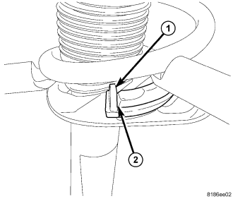
7. Install the strut (3) up through the bottom of the coil spring and upper spring seat, mount, and bearing until the lower spring seat contacts the lower end of the coil spring. Rotate the strut as necessary until the end of the bottom coil (2) comes in contact with the stop (1) built into the lower spring isolator.
8. While holding the strut in position, install the nut (1) on the end of the strut rod.
CAUTION: Never use impact or high speed tools to remove the strut rod nut. Damage to the strut internal bearings can occur.
9. Install Strut Nut Wrench (2), Special Tool 9362, on the strut rod nut. Next, install Strut Shaft Socket (1), Special Tool 9894, on the end of the strut rod. While holding the strut rod from turning, tighten the strut rod nut to 60 N·m (44 ft. lbs.) using a torque wrench on the end of Special Tool 9362.
10. Slowly release the tension from the coil spring by backing off the compressor (1) drive completely. As the tension is relieved, make sure the upper mount and bearing align properly. Verify the upper mount does not bind when rotated.
11. Remove the strut assembly from the spring compressor.
12. Install the strut assembly on the vehicle. (Refer to 2 - SUSPENSION/FRONT/STRUT - INSTALLATION)
INSTALLATION
1. Raise the strut assembly (2) into the strut tower, aligning the three studs on the strut assembly upper mount with the holes in strut tower. Install the three mounting nuts (1) on the studs. Tighten the three nuts to 48 N·m (35 ft. lbs.).
CAUTION: The strut assembly-to-knuckle attaching bolts (5) are serrated and must not be turned during installation. Install the nuts while holding the bolts stationary in the knuckle.
2. Position the lower end of the strut assembly (3) in line with the upper end of the knuckle (6), aligning the mounting holes. Install the two attaching bolts (5). Install the nuts (2). While holding the bolts in place, tighten the nuts to 84 N·m (62 ft. lbs.).
3. Attach the stabilizer bar link (1) to the strut (3). Install and tighten the nut (4) while holding the stabilizer bar link stud stationary. Tighten the nut to 58 N·m (43 ft. lbs.).
4. Secure the flex hose (2) routing bracket to the strut (6) with the mounting screw (1). Tighten the mounting screw to 13 N·m (120 in. lbs.).
5. Install the tire and wheel assembly (1) (Refer to 22 - TIRES/WHEELS - INSTALLATION). Install and tighten the wheel mounting nuts (3) to 135 N·m (100 ft. lbs.).
6. Lower the vehicle.
7. Perform wheel alignment as necessary. (Refer to 2 - SUSPENSION/WHEEL ALIGNMENT - STANDARD PROCEDURE)