SWITCH-HEATED SEAT
DESCRIPTION
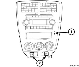
The heated seat switches are located in the center stack (1) of the instrument panel. The switches are located on the outer edges of the accessory switch bank (2). If either of the switches is damaged or inoperative the complete accessory switch bank assembly must be replaced.
When either of the heated seat switches are depressed a switch status message is sent to the Cab Compartment Node (CCN) or instrument cluster via the Local Interface Network (LIN) data bus. The CCN then sends a message via the LIN data bus to the heated seat module, signaling the module to energize the heating element for the selected seat. Amber Light Emitting Diodes (LEDs) in the top portion of each switch indicate the level of heat in use: Two LEDs are illuminated for high, one for low, and none for off. The heated seat module sends the LED illumination message to the CNN via the LIN data bus. The CNN then sends the LED illumination message to the accessory switch bank so that the appropriate LEDs are illuminated for any given heating level. Pressing the switch once will select high-level heating. Pressing the switch a second time will select low-level heating. Pressing the switch a third time will shut the heating elements off.
The LED indicator lamps in each heated seat switch cannot be repaired. If the LED lamps are inoperative or damaged, or the switch is inoperative or damaged the complete accessory switch bank assembly must be replaced.
OPERATION
The heated seat switches are active any time the Local Interface Network (LIN) data bus is active. Depressing the heated seat switch provides a switch status message to the Cabin Compartment Node (CCN) via the LIN data bus. The CCN is responsible for supplying the LIN data bus message to the heated seat module, signaling the module to power the heated seat element of the selected seat and maintain the temperature setting. If the heated seat switch is depressed to a different position (Low or High) than the currently selected state, the CCN will go through the process again to change the temperature setting.
REMOVAL
WARNING: On vehicles equipped with airbags, disable the airbag system before attempting any steering wheel, steering column, or instrument panel component diagnosis or service. Disconnect and isolate the negative battery (ground) cable, then wait two minutes for the airbag system capacitor to discharge before performing further diagnosis or service. This is the only sure way to disable the airbag system. Failure to take the proper precautions could result in accidental airbag deployment and possible personal injury or death.
NOTE: The heated seat switches are integral to the accessory switch bezel and cannot be serviced separately.
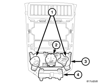
1. Disconnect and isolate the negative battery cable.
2. Remove the center bezel from the instrument panel and place it on a work bench (Refer to 23 - BODY/INSTRUMENT PANEL/BEZEL-CENTER - REMOVAL).
3. Remove the screws that secure the accessory switch bank (4) to the back of the center bezel and remove the accessory switch bank.
INSTALLATION
NOTE: There are different instrument panel accessory switch banks available based on the option content of the vehicle. Ensure the accessory switch bank being installed matches the vehicle options.
1. Position the accessory switch bank (4) onto the back of the instrument panel center bezel.
2. Install the screws that secure the accessory switch bank to the center bezel. Tighten the screws to 1 N·m (8 in. lbs.).
3. Install the center bezel onto the instrument panel (Refer to 23 - BODY/INSTRUMENT PANEL/BEZEL-CENTER - INSTALLATION).
4. Reconnect the negative battery cable.
5. Verify heated seat system operation.