SWITCH-SUNROOF
DESCRIPTION
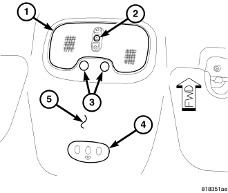
The power sunroof switch (2) is a combination push-button and rocker switch module mounted in the Courtesy/Reading Lamp assembly (1). The sunroof switch is a direct contact unit that is directly wired to the sunroof motor/module assembly. The sunroof switch performs the following functions:
- Power sunroof open (back of switch pushed)
- Power sunroof express open (back of switch pushed and released)
- Power sunroof closed (front of switch pushed)
- Power sunroof express closed (front of switch pushed and released)
- Power sunroof vent (switch center button pushed)
The power sunroof switch cannot be repaired. If the individual components are damaged or inoperative the switch assembly must be replaced, (Refer to 8 - ELECTRICAL/POWER TOP/SWITCH - REMOVAL).
OPERATION
The sunroof is electrically operated from two switches located in the headliner on the courtesy/reading lamp assembly. The power sunroof switch is hard wired to the sunroof motor/module assembly. The “VENT” switch is a push button type switch and opens the sunroof to the vent position only. The other switch “OPEN/CLOSED” is a rocker type switch for opening and closing the sunroof. Pressing and releasing the open button once, the sunroof will express open and the wind deflector will raise. If the button is pressed a second time the sunroof will stop in that position. Pressing and releasing the close button once will express close the sunroof. If the close button is pressed a second time during the express close operation the sunroof will stop in that position.
The switch is grounded at one terminal and receives a 5 volt signal from the sunroof motor/module on the remaining three terminals. The switch pulls down the 5 volt reference voltage from the module signaling it to perform the desired function.
For complete circuit diagrams, refer to the appropriate wiring information. The wiring information includes wiring diagrams, proper wire and connector repair procedures, details of wire harness routing and retention, connector pin-out information and location views for the various wire harness connectors, splices and grounds.
REMOVAL
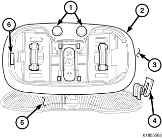
1. Disconnect and isolate the negative battery cable.
2. Remove the courtesy/reading lamp lens (5). Insert a suitable flat bladed tool into the slot (6) in the courtesy/reading lamp assembly (2). Pivot the lens down and to the left to release the holding tab (4).
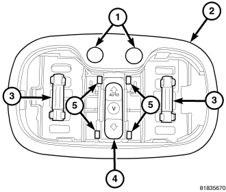
3. Using a suitable flat bladed tool, release the mounting tabs (5) from the sides of the sunroof control switch (4) and pull the switch down from the courtesy/reading lamp assembly (2).
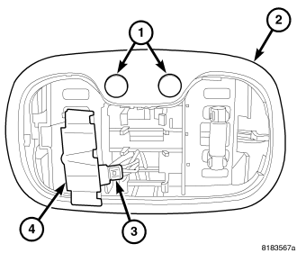
4. Disconnect the electrical connector (3) from the sunroof control switch (4).
5. Remove the switch from the vehicle.
INSTALLATION
1. Position the sunroof control switch (4) into the vehicle.
2. Connect the sunroof control switch electrical connector (3).
3. Insert the sunroof control switch (4) into the courtesy/reading lamp assembly (2). Push up on the switch until it is securely held in place by the mounting tabs (5).
4. Insert the mounting tab (4) on the lamp lens (5) into the right side of the lamp assembly and pivot the lens up until it snaps securely in place.
5. Connect the negative battery cable.