INSTALLATION
FRONT
CAUTION: Do not apply pressure to, or pry on, the plastic drive link bushings. When removing the drive link from, or installing the drive link to the ball stud on the wiper motor crank arm, apply pressure to, or pry on, only the metal portions of the drive link around the bushing. If the bushing is damaged, the entire front wiper module MUST be replaced.
CAUTION: Do not remove the crank arm nut from the wiper motor output shaft. The crank arm is indexed to the output shaft with the motor in the park position during the manufacturing process, but there are no provisions made for correctly indexing this connection in the field. If the crank arm to output shaft indexing is incorrect, the entire front wiper module MUST be replaced.
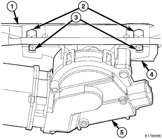
1. Position the front wiper motor and crank arm unit (5) to the underside of the front wiper module bracket (1).
2. Install and tighten the two screws (2) into the two nuts (3) that secure the motor bracket (4) to the module bracket. Tighten the screws to 7.5 N·m (66 in. lbs.).
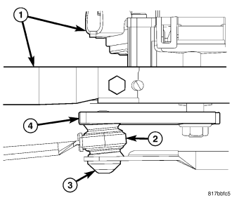
3. Position the sleeve bushing (2) of the driver side wiper drive link onto the ball stud on the end of the motor crank arm (4).
4. Position the socket bushing (3) of the passenger side wiper drive link over the ball stud on the crank arm.
5. Place a short 19 millimeter or 3/4 inch socket over the domed cap side of the socket bushing as an installation tool. Use large channel-lock pliers to firmly and evenly apply enough pressure to the underside of the crank arm and the top of the socket installation tool to snap the bushing onto the ball stud. Do not apply pressure directly to the plastic bushings.
NOTE: Be certain to turn the ignition switch to the ON position, then turn the front wiper switch ON and OFF again to cycle the wiper motor and linkage to their natural park position before reinstalling the front wiper arms onto the wiper pivots.
6. Reinstall the front wiper module (1) into the vehicle. (Refer to 8 - ELECTRICAL/WIPERS/WASHERS/WIPER MODULE - INSTALLATION/FRONT WIPER MODULE).
7. Reconnect the battery negative cable.
REAR
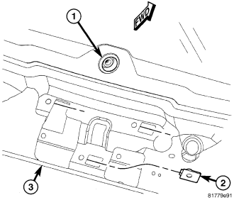
1. Install a new rubber grommet (1) into the rear wiper motor output shaft clearance hole located in the liftgate glass. Always use a new rubber grommet in the glass.
2. Check to be certain that the three U-nuts (2) are properly installed and in good condition in the liftgate inner panel (3).
CAUTION: A new replacement rear wiper motor is shipped with a rubber lubricant applied to the motor output shaft where it contacts the rubber grommet in the liftgate glass. If a rear wiper motor is removed then reinstalled, an appropriate rubber lubricant (Mopar® Nye Synthetic Lubricant - also known as Fluorocarbon Gel 880 Synthetic Lubricant) must be applied to the motor output shaft in the area just below the taper where the shaft will contact the grommet before the motor is reinstalled. Failure to comply with this caution can result in premature grommet failure, excessive motor loads and water leaks.
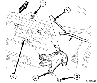
3. Insert the rear wiper motor (4) output shaft through the rubber grommet (1) in the liftgate glass.
4. Position the rear wiper motor and mounting bracket to the U-nuts (5) in the liftgate inner panel as a unit
5. Install and tighten the three screws (3) that secure the motor mounting bracket to the liftgate. Tighten the screws to 7 N·m (62 in. lbs.).
6. Reconnect the liftgate wire harness connector (2) to the wiper motor connector receptacle.
7. Reinstall the trim onto the liftgate inner panel. (Refer to 23 - BODY/DECKLID/HATCH/LIFTGATE/TAILGATE/TRIM PANEL - INSTALLATION).
8. Reinstall the rear wiper arm onto the output shaft. (Refer to 8 - ELECTRICAL/WIPERS/WASHERS/WIPER ARMS - INSTALLATION - REAR).
9. Reconnect the battery negative cable.