COOLER-CHARGE AIR AND PLUMBING
- DESCRIPTION
- OPERATION
- DIAGNOSIS AND TESTING - CHARGE AIR COOLER SYSTEM - LEAKS
- REMOVAL - CHARGE AIR COOLER
- INSPECTION
- INSTALLATION
DESCRIPTION
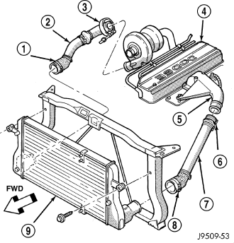
The charge air system consists of a inlet air compressor which is part of the turbocharger housing, charge air cooler locate in front of the radiator, and charge air cooler plumbing. The is also a electronic control valve placed after the charge air cooler, inline, that assists with air flow during the EGR operating mode.
The charge air cooler is a heat exchanger that uses air flow from vehicle motion to dissipate heat from the intake air. As the turbocharger increases air pressure, the air temperature increases. Lowering the intake air temperature increases engine efficiency and power. Refer to (Refer to 11 - EXHAUST SYSTEM/TURBOCHARGER SYSTEM - OPERATION).
OPERATION
Intake air is drawn through the air cleaner and into the turbocharger compressor housing. Once inside the housing the air is compressed by the rotation of the turbine wheel. The turbine wheel is driven by exhaust gasses, Refer to (Refer to 11 - EXHAUST SYSTEM/TURBOCHARGER SYSTEM - OPERATION) to understand the turbine speed operation.
This air compression process causes heat. Pressurized air (charge air) from the turbocharger then flows forward through the charge air cooler, located in front of the radiator, to be cooled by the air flow from vehicle motion rushing past the cooler fins. From the charge air cooler the air flows back into the intake manifold, past an air control valve that assists in EGR mode. There are also resonators located in the charge air stream that assist with air flow and noise suppression.
DIAGNOSIS AND TESTING - CHARGE AIR COOLER SYSTEM - LEAKS
NOTE: Slight engine oil pooling in the charge air inlet hose IS NOT premature turbocharger failure. Slight pooling is the normal result of the breather system. Test the air breather tube for normal operation by referring to the appropriate diagnostic manual.
Low turbocharger boost pressure and low engine performance can be caused by leaks in the charge air cooler or it's plumbing. The following procedure outlines how to check for leaks in the charge air cooler system.
1. Loosen clamp and remove turbocharger to air inlet duct rubber sleeve from turbocharger.
2. Insert Special Tool 9556 Adapter into the rubber sleeve. Tighten existing clamp to 8 N·m (72 in. lbs.).
3. Separate the breather hose at the breather heater and block off.
4. Remove the oil level indicator and block off tube.
CAUTION: Do not apply more then 0.6 bar (10 psi) air pressure to the charge air cooler system, sever damage to the charge air cooler system may occur.
5. Connect regulated air supply to air fitting on Special Tool 9556 Adapter. Set air pressure to approximately 0.6 bar (10 psi).
6. Using soapy water check the air inlet ducts, rubber sleeves, charge air cooler and intake manifold for leaks.
REMOVAL - CHARGE AIR COOLER
WARNING: IF THE ENGINE WAS JUST TURNED OFF, THE AIR INTAKE SYSTEM TUBES MAY BE HOT.
NOTE: Note the location of the rubber air charge cooler to A/C condenser and air charger cooler to radiator air seals. The seals are use to prevent overheating and improve charge air and A/C efficiency.
1. Disconnect the battery negative cables.
2. Remove cooling module (Refer to 7 - COOLING/ENGINE/RADIATOR - REMOVAL).
3. Remove the front grill.
4. Mark the position of the radiator upper cross member and remove cross member.
5. Unbolt the transmission auxiliary cooler and power steering cooler from the charge air cooler and set aside.
6. Remove the boost tubes from the charge air cooler.
7. Remove power steering reservoir retaining bolt, and set reservoir aside.
8. Remove the charge air cooler bolts.
NOTE: Care must be taken not to damage the charge air cooler fins and the fins of other ancillary cooler components.
9. Pivot the charge air cooler rearward and up to remove.
INSPECTION
Visually inspect the charge air cooler and plumbing for cracks, holes, loose clamps, or damage. Inspect the tubes, fins, and welds for tears, breaks, or other damage. Replace the charge air cooler if damage is found.
Pressure test the charge air cooler, using Charge Air Cooler Tester Kit.
INSTALLATION
1. Position the power steering reservoir along with charge air cooler. Install the bolts and tighten to 2 N·m (17 in. lbs.).
2. Install cooling module (Refer to 7 - COOLING/ENGINE/RADIATOR - INSTALLATION) (Refer to 7 - COOLING/ENGINE/RADIATOR FAN - INSTALLATION).
3. Install the transmission auxiliary cooler (if equipped) (Refer to 7 - COOLING/TRANSMISSION/TRANS COOLER - INSTALLATION).
4. Install the power steering cooler.
5. Install the boost tubes to the charge air cooler . With the clamps in position, tighten the clamps to 11 N·m (95 in. lbs.)
6. Align and install upper cross member .
7. Install the front grill (Refer to 23 - BODY/EXTERIOR/GRILLE - INSTALLATION) .
8. Connect the battery negative cable.
9. Start engine and check for leaks.