BODY-VALVE
DESCRIPTION
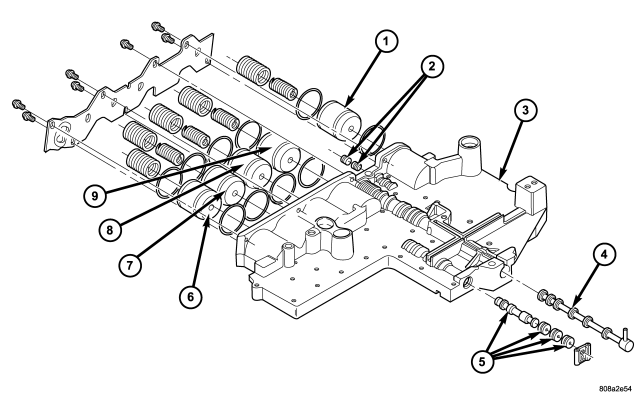
| Valve Body Components |
| 1 - LOW/REVERSE ACCUMULATOR |
6 - OVERDRIVE ACCUMULATOR |
| 2 - LOW/REVERSE SHUTTLE VALVE |
7 - UNDERDRIVE ACCUMULATOR |
| 3 - UPPER VALVE BODY |
8 - 4C ACCUMULATOR |
| 4 - MANUAL VALVE |
9 - 2C ACCUMULATOR |
| 5 - SOLENOID SWITCH VALVE |
The valve body consists of a cast aluminum valve body, a separator plate, and a transfer plate. The valve body contains valves and check balls that control fluid delivery to the torque converter clutch, bands, and frictional clutches. The valve body contains the following components :
- Solenoid switch valve
- Manual valve
- Low/reverse shuttle valve
- 5 Accumulators
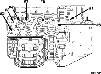
- 7 check balls
OPERATION
NOTE: Refer to the Hydraulic Schematics for a visual aid in determining valve location, operation and design.
SOLENOID SWITCH VALVE
The Solenoid Switch Valve (SSV) controls the direction of the transmission fluid when the L/R-TCC solenoid is energized.
The Solenoid Switch Valve controls line pressure from the LR-TCC solenoid. In 1st gear, the SSV will be in the downshifted position, thus directing fluid to the L/R clutch circuit. In 2nd, 3rd, 4th, and fifth gears, the solenoid switch valve will be in the upshifted position and directs the fluid into the torque converter clutch (TCC) circuit.
When shifting into 1st gear, a special hydraulic sequence is performed to ensure SSV movement into the downshifted position. The L/R pressure switch is monitored to confirm SSV movement. If the movement is not confirmed (the L/R pressure switch does not close), 2nd gear is substituted for 1st. A DTC will be set after three unsuccessful attempts are made to get into 1st gear in one given key start.
MANUAL VALVE
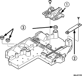
| 1 - TRS SELECTOR PLATE |
| 2 - DETENT SPRING |
| 3 - CLUTCH PASSAGE SEALS |
The manual valve is a relay valve. The purpose of the manual valve is to direct fluid to the correct circuit needed for a specific gear or driving range. The manual valve, as the name implies, is manually operated by the driver with a lever located on the top of the valve body. The valve is connected mechanically by a cable to the gearshift mechanism. The valve is held in each of its positions by a roller detent spring (2) that engages the roostercomb of the TRS selector plate (1).
LOW/REVERSE SWITCH VALVE
The low/reverse switch valve allows the low/reverse clutch to be operated by either the LR/CC solenoid or the MS solenoid.
REMOVAL
NOTE: The valve body can be removed for service without having to remove the transmission assembly. The valve body can be disassembled for cleaning and inspection of the individual components. (Refer to 21 - TRANSMISSION/AUTOMATIC - 45RFE/VALVE BODY - DISASSEMBLY)
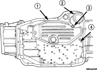
1. Shift transmission into PARK.
2. Raise vehicle.
3. Disconnect wires at the solenoid and pressure switch assembly 23 pin electrical connector.
4. Position drain pan under transmission oil pan.
5. Remove transmission oil pan.
6. Remove the primary oil filter (1) from valve body.
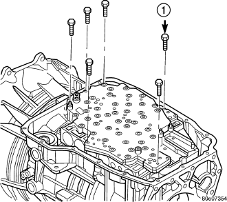
7. Remove bolts (1) attaching valve body to transmission case.
8. Lower the valve body and work the electrical connector out of transmission case.
9. Separate the valve body from the transmission.
DISASSEMBLY
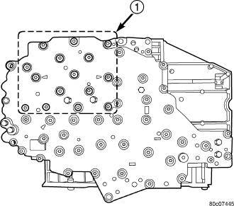
1. Remove the bolts (1) holding the solenoid and pressure switch assembly to the valve body. Do not remove the screws on the top of the solenoid and pressure switch assembly.
2. Separate the solenoid and pressure switch assembly from the valve body.
| 1 - TRS SELECTOR PLATE |
| 2 - DETENT SPRING |
| 3 - CLUTCH PASSAGE SEALS |
3. Remove the screw holding the detent spring (2) onto the valve body.
4. Remove the detent spring (2) from the valve body.
5. Remove the TRS selector plate (1) from the valve body and the manual valve.
6. Remove the clutch passage seals (3) from the valve body, if necessary.
| Valve Body Components |
| 1 - LOW/REVERSE ACCUMULATOR | 6 - OVERDRIVE ACCUMULATOR |
| 2 - LOW/REVERSE SHUTTLE VALVE | 7 - UNDERDRIVE ACCUMULATOR |
| 3 - UPPER VALVE BODY | 8 - 4C ACCUMULATOR |
| 4 - MANUAL VALVE | 9 - 2C ACCUMULATOR |
| 5 - SOLENOID SWITCH VALVE |
7. Remove the screws holding the accumulator cover onto the valve body .
8. Remove the accumulator springs and pistons (1, 6-9) from the valve body. Note which accumulator piston and spring belong in each location.
9. Place the valve body on the bench with the transfer plate upward.
NOTE: The valve body contains seven check balls. The transfer plate must be placed upward to prevent losing the check balls when the transfer plate is removed from the valve body.
10. Remove the screws holding the valve body to the valve body transfer plate.
11. Remove the transfer plate from the valve body. Note the location of all check balls .
12. Remove the check balls from the valve body.
| Valve Body Components |
| 1 - LOW/REVERSE ACCUMULATOR | 6 - OVERDRIVE ACCUMULATOR |
| 2 - LOW/REVERSE SHUTTLE VALVE | 7 - UNDERDRIVE ACCUMULATOR |
| 3 - UPPER VALVE BODY | 8 - 4C ACCUMULATOR |
| 4 - MANUAL VALVE | 9 - 2C ACCUMULATOR |
| 5 - SOLENOID SWITCH VALVE |
13. Remove the retainers securing the solenoid switch valve (5), manual valve (4), and the low/reverse switch valve (2) from the valve body and remove the associated valve and spring. Tag each valve and spring combination with location information to aid in assembly.
CLEANING
| Valve Body Components |
| 1 - LOW/REVERSE ACCUMULATOR |
6 - OVERDRIVE ACCUMULATOR |
| 2 - LOW/REVERSE SHUTTLE VALVE |
7 - UNDERDRIVE ACCUMULATOR |
| 3 - UPPER VALVE BODY |
8 - 4C ACCUMULATOR |
| 4 - MANUAL VALVE |
9 - 2C ACCUMULATOR |
| 5 - SOLENOID SWITCH VALVE |
Clean the valve housings, valves, plugs, springs, and separator plates with a standard parts cleaning solution only. Do not use gasoline, kerosene, or any type of caustic solution.
Do not immerse any of the electrical components in cleaning solution. Clean the electrical components by wiping them off with dry shop towels only.
Dry all except the electrical parts with compressed air. Make sure all passages are clean and free from obstructions. Do not use rags or shop towels to dry or wipe off valve body components. Lint from these materials can stick to valve body parts, interfere with valve operation, and clog filters and fluid passages.
INSPECTION
| Valve Body Components |
| 1 - LOW/REVERSE ACCUMULATOR |
6 - OVERDRIVE ACCUMULATOR |
| 2 - LOW/REVERSE SHUTTLE VALVE |
7 - UNDERDRIVE ACCUMULATOR |
| 3 - UPPER VALVE BODY |
8 - 4C ACCUMULATOR |
| 4 - MANUAL VALVE |
9 - 2C ACCUMULATOR |
| 5 - SOLENOID SWITCH VALVE |
NOTE: Only the INNER accumulator seal ring actually seals the pressure in the bore. The outer seal ring only serves to guide the piston in the bore. Gouges which do not extend past the inner seal ring (and have no raised edges, which could damage the guide ring) are acceptable. The machined accumulator bores often have a tiger-striped appearance. This is NORMAL and does NOT require replacement, as long as the bores are smooth in the inner seal ring area.
Inspect all of the valve body mating surfaces for scratches, nicks, burrs, or distortion. Use a straightedge to check surface flatness. Minor scratches may be removed with crocus cloth using only very light pressure.
Minor distortion of a valve body mating surface may be corrected by smoothing the surface with a sheet of crocus cloth. Position the crocus cloth on a surface plate, sheet of plate glass or equally flat surface. If distortion is severe or any surfaces are heavily scored, the valve body will have to be replaced.
Inspect the valves and plugs for scratches, burrs, nicks, or scores. Minor surface scratches on steel valves and plugs can be removed with crocus cloth but do not round off the edges of the valve or plug lands. Maintaining sharpness of these edges is vitally important. The edges prevent foreign matter from lodging between the valves and plugs and the bore.
Inspect all the valve and plug bores in the valve body. Use a penlight to view the bore interiors. Replace the valve body if any bores are distorted or scored. Inspect all of the valve body springs. The springs must be free of distortion, warpage or broken coils.
Trial fit each valve and plug in its bore to check freedom of operation. When clean and dry, the valves and plugs should drop freely into the bores.
Valve body bores do not change dimensionally with use. If the valve body functioned correctly when new, it will continue to operate properly after cleaning and inspection. It should not be necessary to replace a valve body assembly unless it is damaged in handling.
Inspect all the accumulator bores in the valve body. Use a penlight to view the bore interiors. Replace the valve body if any bores are distorted or scored. Inspect all of the accumulator springs. The springs must be free of distortion, warpage or broken coils.
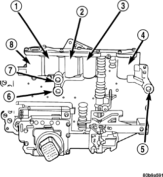
| 1 - UNDERDRIVE ACCUMULATOR (2 SPRINGS) |
| 2 - 4TH CLUTCH ACCUMULATOR (2 SPRINGS) |
| 3 - 2ND CLUTCH ACCUMULATOR (2 SPRINGS) |
| 4 - LOW REVERSE ACCUMULATOR (2 SPRINGS) |
| 5 - LOW/REVERSE PASSAGE SEAL |
| 6 - 2ND CLUTCH PASSAGE SEAL |
| 7 - 4TH CLUTCH PASSAGE SEAL |
| 8 - OVERDRIVE ACCUMULATOR (1 SPRING) |
Inspect all the fluid seals on the valve body. Replace any seals that are cracked, distorted, or damaged in any way. These seals pass fluid pressure directly to the clutches. Any pressure leak at these points, may cause transmission performance problems.
ASSEMBLY
| Valve Body Components |
| 1 - LOW/REVERSE ACCUMULATOR | 6 - OVERDRIVE ACCUMULATOR |
| 2 - LOW/REVERSE SHUTTLE VALVE | 7 - UNDERDRIVE ACCUMULATOR |
| 3 - UPPER VALVE BODY | 8 - 4C ACCUMULATOR |
| 4 - MANUAL VALVE | 9 - 2C ACCUMULATOR |
| 5 - SOLENOID SWITCH VALVE |
1. Lubricate valves and the housing valve bores with clean transmission fluid.
2. Install solenoid switch valve (5) and manual valve (4) into the valve body.
3. Install the retainers to hold each valve into the valve body.
4. Install the valve body check balls into their proper locations.
5. Position the separator and transfer plate onto the valve body.
6. Install the screws to hold the transfer plate to the valve body. Tighten the screws to 6 N·m (50 in. lbs.).
| Valve Body Components |
| 1 - LOW/REVERSE ACCUMULATOR | 6 - OVERDRIVE ACCUMULATOR |
| 2 - LOW/REVERSE SHUTTLE VALVE | 7 - UNDERDRIVE ACCUMULATOR |
| 3 - UPPER VALVE BODY | 8 - 4C ACCUMULATOR |
| 4 - MANUAL VALVE | 9 - 2C ACCUMULATOR |
| 5 - SOLENOID SWITCH VALVE |
7. Install the accumulator pistons (1, 6-9) and springs into the valve body in the location from which they were removed. Note that all accumulators except the overdrive have two springs. The overdrive accumulator piston (6) has only one spring.
8. Install the Low / Reverse shuttle valve and retainer into the valve body housing.
9. Position the accumulator cover onto the valve body.
10. Install the screws to hold the accumulator cover onto the valve body. Tighten the screws to 7 N·m (60 in. lbs.).
| 1 - TRS SELECTOR PLATE |
| 2 - DETENT SPRING |
| 3 - CLUTCH PASSAGE SEALS |
11. Install the TRS selector plate (1) onto the valve body and the manual valve.
12. Position the detent spring (2) onto the valve body.
13. Install the screw to hold the detent spring (2) onto the valve body. Tighten the screw to 4.5 N·m (40 in. lbs.).
14. Install new clutch passage seals (3) onto the valve body, if necessary.
15. Install the solenoid and pressure switch assembly onto the valve body.
16. Install the bolts (1) to hold the solenoid and pressure switch assembly onto the valve body. Tighten the bolts to 6 N·m (50 in. lbs.). Tighten the bolts adjacent to the arrows cast into the bottom of the transfer plate first.
INSTALLATION
1. Check condition of seals on valve body and the solenoid and pressure switch assembly. Replace seals if cut or worn.
2. Place TRS selector plate in the PARK position.
3. Place the transmission in the PARK position.
4. Lubricate seal on the solenoid and pressure switch assembly connector with petroleum jelly.
5. Position valve body in transmission and align the manual lever on the valve body to the pin on the transmission manual shift lever.
6. Seat valve body in case and install one or two bolts to hold valve body in place.
7. Tighten valve body bolts alternately and evenly to 12 N·m (105 in. lbs.) torque.
8. Operate the external manual shift lever and ensure that the TRS selector plate moves correctly into all gear range positions.
CAUTION: The primary oil filter seal MUST be fully installed flush against the oil pump body. DO NOT install the seal onto the filter neck and attempt to install the filter and seal as an assembly. Damage to the transmission will result.
9. Install a new primary oil filter seal in the oil pump inlet bore. Seat the seal in the bore with the butt end of a hammer, or other suitable tool.
10. Place replacement filter (1) in position on valve body and into the oil pump.
11. Install screw to hold filter to valve body. Tighten screw to 4.5 N·m (40 in. lbs.) torque.
12. Connect the solenoid and pressure switch 23 pin electrical assembly connector.
13. Install oil pan using silicone gasket sealer. Tighten pan bolts to 12 N·m (105 in. lbs.) torque.
14. Lower vehicle and fill transmission with Mopar® ATF +4.
15. Check and adjust gearshift cable, if necessary.