ACTUATOR-MODE DOOR
DESCRIPTION
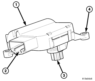
This vehicle uses two mode door actuators (1) which are reversible, 12-volt direct current (DC), servo motors. The mode door actuator for the panel/defrost/demist/floor air doors is located on the driver side end of the HVAC air distribution housing. The mode door actuator for the rear floor/console air door is located on the rear of the air distribution housing near the front of the floor console area. The mode door actuators are mechanically connected to the mode-air doors.
The mode door actuator is interchangeable with the actuators for the blend-air door(s) and the recirculation-air door. Each actuator is contained within an identical black molded plastic housing with an integral wire connector receptacle (2). Each actuator also has an identical output shaft with splines (3) that connects it to its door linkage and three integral mounting tabs (4) that allow the actuator to be secured to the HVAC housing. The mode door actuator does not require mechanical indexing to the mode-air doors, as it is electronically calibrated by the A/C-heater control.
OPERATION
The two mode door actuators are connected to the A/C-heater control through the vehicle electrical system by dedicated two-wire leads and connectors of the HVAC wire harness. The mode door actuators can move the panel/defrost/demist/floor air doors in two directions. When the A/C-heater control pulls the voltage on one side of the motor connection high and the other connection low, the mode-air doors will move in one direction. When the A/C-heater control reverses the polarity of the voltage to the motor, the mode-air doors moves in the opposite direction.
When the A/C-heater control makes the voltage to both connections high or both connections low, the mode-air door stops and will not move. The A/C-heater control uses a pulse-count positioning system to monitor the operation and relative position of the mode door actuators and the mode-air doors. The A/C-heater control learns the mode-air doors stop positions during the calibration procedure and will store a diagnostic trouble code (DTC) for any problems it detects in the mode door actuator circuits.
The mode door actuators cannot be adjusted or repaired and must be replaced if found inoperative or damaged (refer to 24 - HEATING & AIR CONDITIONING - DIAGNOSIS AND TESTING and to 24 - HVAC Electrical Diagnostics for more information).
REMOVAL
WARNING: Disable the airbag system before attempting any steering wheel, steering column, or instrument panel component diagnosis or service. Disconnect and isolate the negative battery (ground) cable, then wait two minutes for the airbag system capacitor to discharge before performing further diagnosis or service. This is the only sure way to disable the airbag system. Failure to take the proper precautions could result in accidental airbag deployment and possible personal injury or death.
NOTE: The heater-A/C system is equipped with two mode door actuators. One for the air doors for the outlets in the instrument panel and one for the air door for the rear seat/console outlets.
PANEL/DEFROST/DEMIST/FLOOR
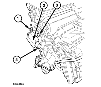
1. Disconnect and isolate the negative battery cable.
2. On LHD models, remove the instrument panel silencer from the driver side of the instrument panel (refer to 23 - BODY/INSTRUMENT PANEL/INSTRUMENT PANEL SILENCER - REMOVAL).
3. On RHD models, remove the glove box from the instrument panel (refer to 23 - BODY/INSTRUMENT PANEL/GLOVE BOX - REMOVAL).
4. Remove the three screws (1) that secure the mode door actuator (2) to the left side of the HVAC air distribution housing (3).
5. Remove the mode door actuator from the air distribution housing and disconnect the HVAC wire harness connector (4) from the actuator.
6. Remove the mode door actuator from the vehicle.
REAR FLOOR/CONSOLE
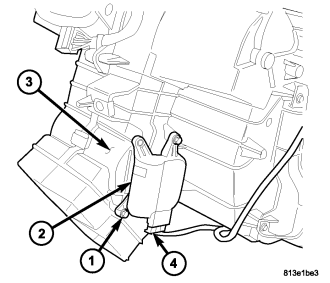
1. Disconnect and isolate the negative battery cable.
2. Remove the instrument panel from the vehicle (refer to 23 - BODY/INSTRUMENT PANEL/INSTRUMENT PANEL ASSEMBLY - REMOVAL).
3. Remove the two screws (1) that secure the mode door actuator (2) to the rear of the HVAC air distribution housing (3).
4. Remove the mode door actuator from the air distribution housing and disconnect the HVAC wire harness connector (4) from the actuator.
5. Remove the mode door actuator from the vehicle.
INSTALLATION
PANEL/DEFROST/DEMIST/FLOOR
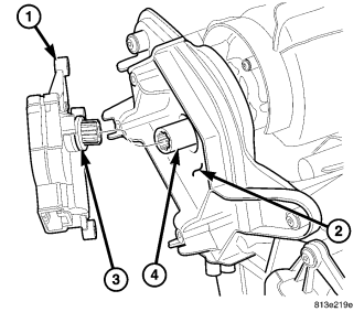
1. Position the mode door actuator (1) into the vehicle.
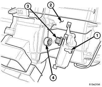
2. Install the mode door actuator onto the left side of the HVAC air distribution housing (2). If necessary, rotate the actuator slightly to align the splines on the actuator output shaft (3) with those on the mode door cam (4).
3. Install the screws (1) that secure the mode door actuator (2) to the left side of the air distribution housing (3). Tighten the screws to 2 N·m (17 in. lbs.).
4. Connect the HVAC wire harness connector (4) to the mode door actuator.
5. On LHD models, install the instrument panel silencer onto the driver side of the instrument panel (refer to 23 - BODY/INSTRUMENT PANEL/INSTRUMENT PANEL SILENCER - INSTALLATION).
6. On RHD models, install the glove box into the instrument panel (refer to 23 - BODY/INSTRUMENT PANEL/GLOVE BOX - INSTALLATION).
7. Reconnect the negative battery cable.
REAR FLOOR/CONSOLE
1. Position the mode door actuator (1) into the vehicle.
2. Install the mode door actuator onto the rear of the HVAC air distribution housing (2). If necessary, rotate the actuator slightly to align the splines on the actuator output shaft (3) with those on the pivot shaft of the rear floor/console air door (4).
3. Install the two screws (1) that secure the mode door actuator (2) to the rear of the air distribution housing (3). Tighten the screws to 2 N·m (17 in. lbs.).
4. Connect the HVAC wire harness connector (4) to the mode door actuator.
5. Install the instrument panel (refer to 23 - BODY/INSTRUMENT PANEL/INSTRUMENT PANEL ASSEMBLY - INSTALLATION).
6. Reconnect the negative battery cable.