OUTLETS-AIR
DESCRIPTION
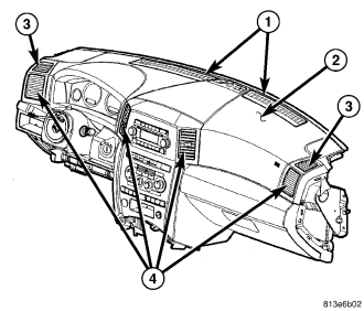
NOTE: LHD model shown. RHD model similar.
There are two defroster air outlets (1) located on the top of the instrument panel (2). The airflow from the defroster outlets is directed by fixed vanes in the defroster grilles and cannot be adjusted. The defroster grilles are serviced individually, however, the defroster outlets are not serviceable from the instrument panel top cover (refer to 23 - BODY/INSTRUMENT PANEL/INSTRUMENT PANEL TOP COVER - REMOVAL).
There are two side window demister air outlets (3). One located on each end of the instrument panel top cover. The airflow from the side window demister air outlets is directed by fixed vanes in the outlets and cannot be adjusted. The side window demister air outlets are not serviceable from the instrument panel top cover (refer to 23 - BODY/INSTRUMENT PANEL/INSTRUMENT PANEL TOP COVER - REMOVAL).
There are four instrument panel air outlets (4). One air outlet is located near each outboard end of the instrument panel facing the rear of the vehicle and one outlet is located on each side of the radio bezel. Each of the instrument panel air outlets contain a non-serviceable grille with movable vanes that are used to direct or shut off the flow of the conditioned air leaving the instrument panel outlets. Only the outboard instrument panel air outlets can be serviced separately. For service of the center instrument panel air outlets, the radio bezel must be replaced.
REMOVAL
WARNING: Disable the airbag system before attempting any steering wheel, steering column, or instrument panel component diagnosis or service. Disconnect and isolate the battery negative (ground) cable, then wait two minutes for the airbag system capacitor to discharge before performing further diagnosis or service. This is the only sure way to disable the airbag system. Failure to take the proper precautions could result in accidental airbag deployment and possible personal injury or death.
NOTE: Only the outboard instrument panel air outlets can be serviced separately. The outboard air outlets can be serviced from underneath the instrument panel by loosening the upper and lower instrument panel covers.
NOTE: LHD model shown in illustrations. RHD model similar.
DRIVER SIDE
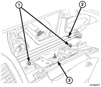
1. Disconnect and isolate the negative battery cable.
2. Remove the instrument cluster (refer to 8 - ELECTRICAL/INSTRUMENT CLUSTER - REMOVAL).
3. Remove the two screws (1) that secure the upper instrument panel cover (2) to the steering column support (3).
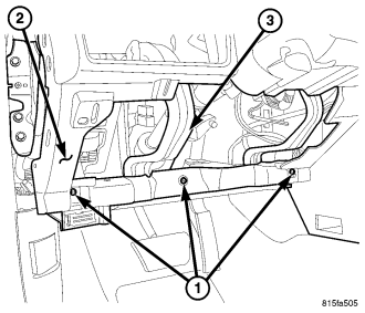
4. Remove the knee blocker from the driver side of the instrument panel.
5. Remove the three screws (1) that secure the lower instrument panel cover (2) to the bottom of the instrument panel support (3).
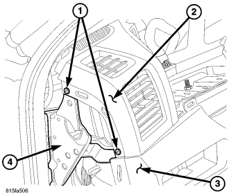
6. Remove the end cap from the driver side of the instrument panel.
7. Remove the storage bin from the driver side of the instrument panel.
8. Remove the screws (1) that secure the upper instrument panel cover (2) and the lower instrument panel cover (3) to the driver side end of the instrument panel support (4).
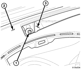
9. Remove the defroster grille from the top of the instrument panel.
10. Through the defroster grille opening, remove the nut (1) that secures the instrument panel (2) to the dash panel (3).
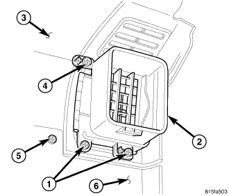
NOTE: Illustration shown with duct removed for clarity.
11. From underneath of the instrument panel, remove the two screws (1) that secure the bottom of the air outlet (2) to the back side of the instrument panel top cover (3) and the one screw (5) that secures the instrument panel top cover to the lower cover (6).
12. Through the opening in the instrument panel cluster area, remove the one screw (4) that secures the top of the air outlet to the back side of the instrument panel top cover.
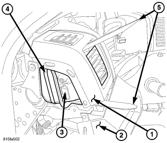
13. Carefully separate the upper instrument panel cover (1) from the lower instrument panel cover (2) to gain access to the outboard air outlet (3).
14. Disengage the air outlet from the instrument panel duct (4) using two trim sticks or other suitable wide flat-blade tool (5) and remove the outlet through the bottom of the instrument panel.
PASSENGER SIDE
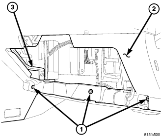
1. Remove the glove box from the instrument panel (refer to 23 - BODY/INSTRUMENT PANEL/GLOVE BOX ASSEMBLY - REMOVAL).
2. Remove the three screws (1) that secure the lower instrument panel cover (2) to the bottom of the instrument panel support (3).
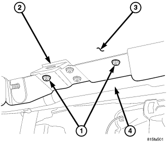
3. Remove the two screws (1) located near the glove box striker (2) that secure the lower instrument panel cover (3) to the instrument panel support (4).
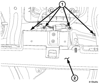
4. Through the glove box opening, remove the four screws (1) that secure the back side of the upper instrument panel cover to the lower instrument panel cover (2).
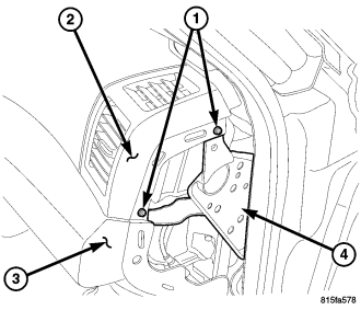
5. Remove the end cap from the passenger side of the instrument panel.
6. Remove the screws (1) that secure the upper instrument panel cover (2) and the lower instrument panel cover (3) to the passenger side end of the instrument panel support (4).
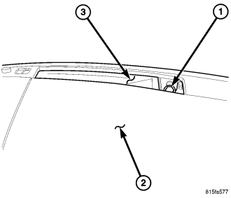
7. Remove the defroster grille from the top of the instrument panel.
8. Through the defroster grille opening, remove the nut (1) that secures the instrument panel (2) to the dash panel (3).
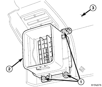
NOTE: Illustration shown with duct removed for clarity.
9. Through the glove box opening, remove the three screws (1) that secure the air outlet (2) to the back side of the instrument panel top cover (3).
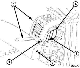
10. Carefully separate the upper instrument panel cover (1) from the lower instrument panel cover (2) to gain access to the outboard air outlet (3).
11. Disengage the air outlet from the instrument panel duct (4) using two trim sticks or other suitable wide flat-blade tool (5) and remove the outlet through the glove box opening.
INSTALLATION
DRIVER SIDE
NOTE: LHD model shown in llustrations. RHD model similar.
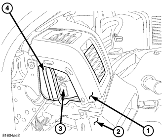
NOTE: Make sure that the air outlet is properly aligned to the instrument panel opening and that the foam seal on the outlet is properly installed.
1. Carefully separate the upper instrument panel cover (1) from the lower instrument panel cover (2) and install the outboard instrument panel air outlet (3) through the bottom of the instrument panel and connect it to the duct (4).
NOTE: Illustration shown with duct removed for clarity.
2. Through the opening in the instrument panel cluster area, install the one screw (4) that secures the top of the air outlet (2) to the back side of the instrument panel top cover (3). Tighten the screw to 2 N·m (17 in. lbs.).
3. From underneath of the instrument panel, install the two screws (1) that secure the bottom of the air outlet to the back side of the instrument panel top cover and the one screw (5) that secures the instrument panel top cover to the lower cover (6).
4. Through the defroster grille opening, install the nut (1) that secures the top of the instrument panel (2) to the dash panel (3). Tighten the nut to 11 N·m (97 in. lbs.).
5. Install the defroster grille onto the instrument panel.
6. Install the screws (1) that secure the upper instrument panel cover (2) and the lower instrument panel cover (3) to the driver side end of the instrument panel support (4). Tighten the screws to 2.2 N·m (20 in. lbs.).
7. Install the storage bin into the driver side of the instrument panel. Make sure the retaining tabs are fully engaged.
8. Install the end cap onto the driver side of the instrument panel. Make sure the retaining tabs are fully engaged.
9. Install the three screws (1) that secure the lower instrument panel cover (2) to the bottom of the instrument panel support (3). Tighten the screws to 2.2 N·m (20 in. lbs.).
10. Install the knee blocker onto the driver side of the instrument panel.
11. Install the two screws (1) that secure the upper instrument panel cover (2) to the steering column support (3). Tighten the screws to 2.2 N·m (20 in. lbs.).
12. Install the instrument cluster (refer to 8 - ELECTRICAL/INSTRUMENT CLUSTER - INSTALLATION).
13. Reconnect the negative battery cable.
PASSENGER SIDE
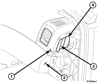
NOTE: Make sure that the air outlet is properly aligned to the instrument panel opening and that the foam seal on the outlet is properly installed.
1. Carefully separate the upper instrument panel cover (1) from the lower instrument panel cover (2) and install the outboard instrument panel air outlet (3) through the glove box opening and connect it to the duct (4).
NOTE: Illustration shown with duct removed for clarity.
2. Through the glove box opening, install the three screws (1) that secure the air outlet (2) to the back side of the instrument panel top cover (3). Tighten the screws to 2 N·m (17 in. lbs.).
3. Through the defroster grille opening, install the nut (1) that secures the top of the instrument panel (2) to the dash panel (3). Tighten the nut to 11 N·m (97 in. lbs.).
4. Install the defroster grille onto the instrument panel.
5. Install the screws (1) that secure the upper instrument panel cover (2) and the lower instrument panel cover (3) to the passenger side end of the instrument panel support (4). Tighten the screws to 2.2 N·m (20 in. lbs.).
6. Install the end cap onto the passenger side of the instrument panel. Make sure the retaining tabs are fully engaged.
7. Through the glove box opening, install the four screws (1) that secure the back side of the upper instrument panel cover to the lower instrument panel cover (2). Tighten the screws to 2 N·m (17 in. lbs.).
8. Install the two screws (1) located near the glove box striker (2) that secure the lower instrument panel cover (3) to the instrument panel support (4). Tighten the screws to 2.2 N·m (20 in. lbs.).
9. Install the three screws (1) that secure the lower instrument panel cover (2) to the bottom of the instrument panel support (3). Tighten the screws to 2.2 N·m (20 in. lbs.).
10. Install the glove box (refer to 23 - BODY/INSTRUMENT PANEL/GLOVE BOX - INSTALLATION).