INSTRUMENT CLUSTER
DESCRIPTION
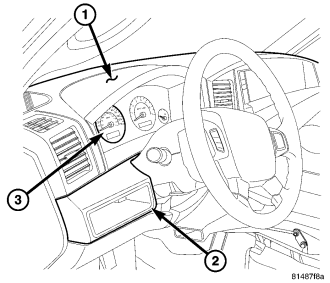
The instrument cluster (3) for this vehicle is an ElectroMechanical Instrument Cluster (EMIC) that is located in the instrument panel above the steering column opening, directly in front of the driver. The remainder of the EMIC, including the mounts and the electrical connections, are concealed within the instrument panel below the cluster hood (1). The instrument cluster for this vehicle also includes the hardware and software necessary to serve as the electronic body control module and is sometimes referred to as the Cab Compartment Node or CCN.
Besides analog gauges and indicators, the EMIC module incorporates two blue-green digital Organic Light Emitting Diode (OLED) display units. One is a fixed segment unit for displaying odometer information, automatic transmission gear selector position (PRNDL), and the cruise indicator. The second is a large, reconfigurable dot matrix unit which serves as the visual display and interface for the Electronic Vehicle Information Center (EVIC), the trip computer, the Universal Garage Door Opener (UGDO), the customer programmable features, numerous textual warning or reminder indicators and certain diagnostic information.
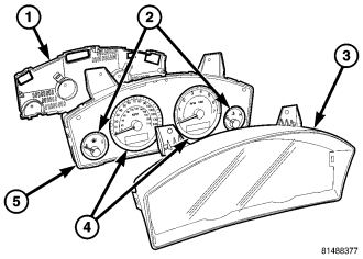
The EMIC gauges and indicators are visible through a dedicated opening in the instrument panel below the cluster hood and are protected by a clear plastic cluster lens and integral hood unit (3). The cluster hood serves as a visor and shields the face of the cluster from ambient light and reflections to reduce glare. The molded plastic lens and hood has a number of integral latch features that secure it to tabs molded into the outer perimeter of the cluster housing. The lens and hood unit also has two integral mounting tabs on the top of the unit. These mounting tabs combined with two on the top of the cluster housing are used to secure the top of the EMIC to the molded plastic instrument panel cluster carrier with two screws.
The rear of the cluster housing (5) and the EMIC electronic circuitry are protected by a molded plastic rear cover (1), which is also secured to the cluster housing by integral latch features. The rear cover includes clearance holes for the cluster connector receptacles. The connector receptacles on the back of the cluster electronic circuit board connect the EMIC to the vehicle electrical system through three take outs with connectors from the instrument panel wire harness.
Sandwiched between the rear cover and the lens and hood unit is the cluster housing. The molded plastic cluster housing serves as the carrier for the cluster circuit board and circuitry, the cluster connector receptacles, the major (4) and minor (2) gauges, a Light Emitting Diode (LED) for each cluster indicator, the two OLED display units, an audible tone transducer, several LED units for general cluster illumination, the cluster overlay, and the gauge pointers. The cluster housing also has two integral mounting posts on its lower surface with rubber isolators used to secure the base of the EMIC to receptacles in the instrument panel cluster carrier.
The cluster overlay is a laminated plastic unit. The dark, visible, outer surface of the overlay is marked with all of the gauge dial faces and graduations, but this layer is also translucent. The darkness of this outer layer prevents the cluster from appearing cluttered or busy by concealing the cluster indicators that are not illuminated, while the translucence of this layer allows those indicators and icons that are illuminated to be readily visible. The underlying layer of the overlay is opaque and allows light from the LED for each of the various indicators and illumination lamps behind it to be visible through the outer layer of the overlay only through predetermined stencil-like cutouts. Rectangular openings in the overlay at the base of the speedometer and tachometer dial faces have smoked clear lenses through which the illuminated OLED display units can be viewed.
Several versions of the EMIC module are offered on this vehicle. These versions accommodate all of the variations of optional equipment and regulatory requirements for the various markets in which the vehicle is offered. The microprocessor-based EMIC utilizes integrated circuitry and information carried on the Controller Area Network (CAN) data bus along with several hard wired analog and multiplexed inputs to monitor sensors and switches throughout the vehicle. In response to those inputs, the internal circuitry and programming of the EMIC allow it to control and integrate many electronic functions and features of the vehicle through both hard wired outputs and the transmission of electronic message outputs to other electronic modules in the vehicle over the CAN data bus. (Refer to 8 - ELECTRICAL/ELECTRONIC CONTROL MODULES/COMMUNICATION - DESCRIPTION - CAN BUS).
Besides typical instrument cluster gauge and indicator support, the electronic functions and features that the EMIC supports or controls include the following:
- A/C Select and Evaporator Probe Support - The EMIC monitors A/C select switch and evaporator temperature sensor hard wired inputs from the Manual Temperature Control (MTC) control or electronic messages received over the CAN data bus from the Automatic Temperature Control (ATC) control, then transmits electronic A/C clutch request messages when appropriate to support the A/C clutch control feature.
- Audible Warnings - The EMIC electronic circuit board is equipped with an audible tone transducer and programming that allows it to provide various audible alerts to the vehicle operator. These alerts include single chime tones and continuous slow or fast tones. An electromechanical relay is also soldered onto the circuit board to produce audible clicks that are used to emulate the sound of a conventional turn signal or hazard warning flasher.
- Automatic Headlamps Support - On vehicles equipped with optional automatic headlamps, the EMIC calculates the average ambient light level based upon either a hard wired input from the sun load sensor on the top of the instrument panel or upon an electronic message received over the CAN data bus from the Rain Sensor Module (RSM) on the windshield below the automatic day/night inside rear view mirror mounting button, then transmits an electronic auto headlamps request message when appropriate to support the automatic headlamps feature.
- Electric Backlight Status Support - On vehicles equipped with optional Automatic Temperature Control (ATC), the EMIC monitors electronic Electric BackLight (EBL) status messages received over the CAN data bus from the ATC control, then transmits electronic EBL status messages when appropriate to support the EBL feature.
- Electronic Vehicle Information Center Support - In addition to the dot matrix Organic Light Emitting Diode (OLED) display, the EMIC provides support for each of the functions and features of the Electronic Vehicle Information Center (EVIC). This includes support for the compass, customer programmable features, textual warnings, Tire Pressure Monitor (TPM), trip computer, Universal Garage Door Opener (UGDO) and the upper instrument panel switch pod inputs that are used to control and configure many of the EVIC displays. This also includes display arbitrator programming, which controls the priorities, sequences, and transition of information that is displayed in the EVIC, particularly when multiple display requests are received simultaneously.
- Enhanced Accident Response Support - The EMIC monitors an input from the Occupant Restraint Controller (ORC) and, following an airbag deployment, will immediately disable the power lock relay output, unlock all doors by activating the power unlock relay output, then enables the power lock relay output if the power lock switch input remains inactive for two seconds. The EMIC also monitors an input from the Powertrain Control Module (PCM) to automatically turn ON the interior lighting after an airbag deployment event, 10 seconds after the vehicle speed is zero. The interior lighting remains illuminated until the ignition switch is turned to the OFF position, at which time the interior lighting returns to normal operation and control. These Enhanced Accident Response System (EARS) features are each dependent upon a functional vehicle electrical system following the vehicle impact event.
- Fuel Level Data Support - The EMIC provides a current source for and receives a hard wired analog input from the fuel level sending unit located on the fuel pump module in the fuel tank. The EMIC uses this input to calculate the proper fuel gauge needle position and to control low fuel indicator operation. Based upon this input, the EMIC also uses electronic messaging to transmit this data over the CAN data bus for use by other electronic modules in the vehicle.
- Heated Seat Switch Support and Switch Indicator Control - On vehicles equipped with optional heated seats, the EMIC monitors hard wired inputs from the heated seat switches in the lower instrument panel switch pod and transmits electronic heated seat request messages over the CAN data bus. This message wakes up the Heated Seat Module (HSM) when the switch is actuated. The EMIC then monitors electronic messages received over the CAN data bus from the HSM to control a high side driver output to the appropriate heated seat switch Light Emitting Diode (LED) indicators.
- Ignition On and Ignition Accessory/On Relay Control - The EMIC monitors hard wired inputs from the ignition switch on the instrument panel, and provides low side driver outputs to control both the ignition ON and ignition ACCESSORY/ON relays in the Junction Block (JB) as appropriate.
- Interior Lamp Load Shedding - The EMIC provides a battery saver feature which will automatically turn OFF all interior lamps if they remain ON after a timed interval of about eight minutes.
- Interior Lighting Control - The EMIC monitors electronic messages and hard wired inputs from the interior lighting switch, the door ajar switches, the liftgate ajar switch, the liftgate flip-up glass ajar switch, the reading lamp switches, and the Sentry Key REmote Entry Module (SKREEM) (also known as the Wireless Control Module/WCM) to provide courtesy lamp control. This includes support for timed illuminated entry with theater-style fade-to-OFF and courtesy illumination DEFEAT features.
- Panel Lamps Dimming Control - The EMIC monitors electronic dimming level messages received from the panel lamps dimmer switch input to the Steering Control Module (SCM) over the CAN data bus, then provides a hard wired 12-volt Pulse-Width Modulated (PWM) output that synchronizes the dimming level of all panel lamps dimmer controlled lamps with that of the cluster general illumination lighting.
- Park Assist Switch Support and Switch Indicator Control - On vehicles equipped with the optional park assist system, the EMIC monitors a hard wired input from the park assist switch in the lower instrument panel switch pod and transmits electronic park assist switch status messages over the CAN data bus. This message tells the park assist module whether the system should be enabled or disabled when the switch is actuated. The EMIC then monitors electronic messages received over the CAN data bus from the park assist module to control a high side driver output to the park assist switch Light Emitting Diode (LED) disable indicator.
- Power Lock System Control - The EMIC monitors inputs from the power lock switches and the Sentry Key REmote Entry Module (SKREEM) (also known as the Wireless Control Module/WCM) to provide control of the power lock motors through high side driver outputs to the door lock and unlock relays. This includes support for rolling door locks (also known as automatic door locks), automatic door unlock, and a door lock inhibit mode.
- Remote Keyless Entry Support - The EMIC supports the Remote Keyless Entry (RKE) system features, including support for the RKE LOCK, UNLOCK (with optional driver-door-only unlock, and unlock-all-doors), PANIC, audible chirp, optical chirp, illuminated entry modes, an RKE programming mode, as well as optional Vehicle Theft Security System (VTSS) arming (when the proper VTSS arming conditions are met) and disarming.
- Vehicle Theft Security System Control - The EMIC monitors inputs from the door ajar switches, the Steering Control Module (SCM), the Sentry Key REmote Entry Module (SKREEM) (also known as the Wireless Control Module/WCM) and, on vehicles so equipped, the intrusion module then provides electronic horn and lighting request messages to the Front Control Module (FCM) located on the Integrated Power Module (IPM) for the appropriate VTSS alarm output features.
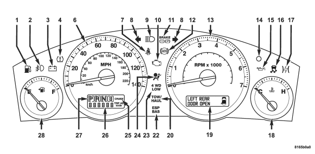
| Except With Diesel Engine Or Rear Fog Lamps |
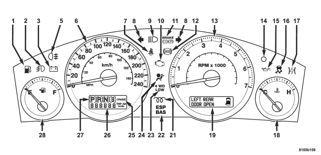
| With Diesel Engine Or Rear Fog Lamps |
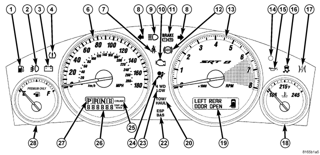
| w/SRT8 |
The EMIC houses 4 analog gauges and has provisions for up to 18 indicators. Some of the EMIC indicators are automatically configured when the EMIC is connected to the vehicle electrical system for compatibility with certain optional equipment or equipment required for regulatory purposes in certain markets. While each EMIC may have provisions for indicators to support every available option, the configurable indicators will not be functional in a vehicle that does not have the equipment that an indicator supports.
The EMIC includes the following analog gauges:
- Engine Temperature Gauge (18)
- Fuel Gauge (28)
- Speedometer (6)
- Tachometer (13)
The EMIC includes the following OLED display units:
- Dot Matrix Display (19) - Electronic Vehicle Information Center (EVIC), Trip Odometer A and B, and Textual Messages
- Fixed Segment Display - Includes Gear Selector Indicator (27), Odometer (26) and Cruise Indicator (25)
The EMIC includes provisions for the following indicators:
- Adjustable Pedal System Indicator - textual messages in dot matrix display (19)
- Airbag Indicator (24)
- Ajar Indicators - textual messages and icon in dot matrix display (19) for doors, hood, liftgate and liftgate flip-up glass
- Antilock Brake System (ABS) Indicator (12)
- Brake Indicator (11)
- Charging Indicator (3)
- Check Gas Cap Indicator - textual message in dot matrix display (19)
- Check Gauges Indicator - textual message in dot matrix display (19)
- Check Shift Procedure Indicator - textual message in dot matrix display (19)
- Coolant Low Indicator - textual message and icon in dot matrix display (19)
- Cruise Indicator (25) - text in fixed segment display
- Electronic Stability Program (ESP)/Brake Assist System (BAS) Indicator (22) - and textual messages in dot matrix display (19)
- Electronic Throttle Control (ETC) Indicator (17)
- Four-Wheel Drive Low Indicator (23)
- Four-Wheel Drive System In Neutral Indicator - textual message and icon in dot matrix display (19)
- Front Fog Lamp Indicator (2)
- Gear Selector Indicator (27)
- High Beam Indicator (9)
- Low Brake Fluid Level Indicator - textual message in dot matrix display (19)
- Low Fuel Indicator (1)
- Low Oil Pressure Indicator (15)
- Malfunction Indicator Lamp (MIL) (10)
- Memory System Indicator - textual messages in dot matrix display (19)
- Oil Pressure Indicator (SRT8 only) - textual message and icon in dot matrix display (19)
- Oil Temperature Indicator (SRT8 only) - textual message and icon in dot matrix display (19)
- Park Assist Disabled Indicator - textual message in dot matrix display (19)
- Perform Service Indicator - textual message in dot matrix display (19)
- Rear Fog Lamp Indicator (5) - in markets where rear fog lamps are available only
- Seat Belt Indicator (7)
- Security Indicator (14) - also textual messages for Sentry Key Immobilizer System (SKIS) in dot matrix display (19)
- Service Column Lock Indicator - textual message in dot matrix display (19)
- Service Exhaust Indicator - textual message in dot matrix display (19) with diesel only
- Service Four-Wheel Drive System Indicator - textual message in dot matrix display (19)
- Service Park Assist System Indicator - textual message in dot matrix display (19)
- SmartBeam® (Auto High Beam) Indicator - textual messages in dot matrix display (19)
- Tire Pressure Monitor (TPM) Indicator (4) - may also include textual messages in dot matrix display (19)
- Tow/Haul Indicator (20)
- Traction Control/Electronic Stability Program (ESP) Indicator (16)
- Transmission Overtemp Indicator - textual message in dot matrix display (19)
- Turn-Signal-On Reminder Indicator - textual message and icon in dot matrix display (19)
- Turn Signal (Right and Left) Indicators (8)
- Upshift Indicator (SRT8 only) - textual message and icon in dot matrix display (19)
- Wait-To-Start Indicator (21) - with diesel only
- Washer Fluid Indicator - textual message and icon in dot matrix display (19)
- Water-In-Fuel Indicator - textual message in dot matrix display (19) with diesel only
Each indicator in the EMIC, except those located within an OLED display unit, is illuminated by a dedicated LED that is soldered onto the EMIC electronic circuit board. Cluster illumination is accomplished by several dimmable LED units, which illuminate each of the gauge dial faces for visibility when the exterior lighting is turned ON. These LED units are not available for service replacement and, if damaged or ineffective, the entire EMIC must be replaced.
Hard wired circuitry connects the EMIC to the electrical system of the vehicle. These hard wired circuits are integral to several wire harnesses, which are routed throughout the vehicle and retained by many different methods. These circuits may be connected to each other, to the vehicle electrical system and to the EMIC through the use of a combination of soldered splices, splice block connectors, and many different types of wire harness terminal connectors and insulators. Refer to the appropriate wiring information. The wiring information includes wiring diagrams, proper wire and connector repair procedures, further details on wire harness routing and retention, as well as pin-out and location views for the various wire harness connectors, splices and grounds.
The EMIC module for this vehicle is serviced only as a complete unit. The EMIC module cannot be adjusted or repaired. If a gauge, an LED unit, an OLED display unit, the electronic circuit board, the circuit board hardware, the cluster overlay, or the EMIC housing are damaged or ineffective, the entire EMIC module must be replaced. The cluster lens, hood and mask unit is available for separate service replacement.
OPERATION
The ElectroMechanical Instrument Cluster (EMIC) in this vehicle also includes the hardware and software necessary to serve as the electronic body control module and is sometimes referred to as the Cab Compartment Node or CCN. The following information deals primarily with the instrument cluster functions of this unit. Additional details of the electronic body control functions of this unit may be found within the service information for the system or component that the EMIC controls. For example: Additional details of the audible warning functions of the EMIC are found within the Chime/Buzzer service information.
The EMIC is designed to allow the vehicle operator to monitor the conditions of many of the vehicle components and operating systems. The gauges and indicators in the EMIC provide valuable information about the various standard and optional powertrains, fuel and emissions systems, cooling systems, lighting systems, safety systems and many other convenience items. The EMIC is installed in the instrument panel so that all of these monitors can be easily viewed by the vehicle operator when driving, while still allowing relative ease of access for service.
The microprocessor-based EMIC hardware and software uses various inputs to control the gauges and indicators visible on the face of the cluster. Some of these inputs are hard wired, but most are in the form of electronic messages that are transmitted by other electronic modules over the Controller Area Network (CAN) data bus. (Refer to 8 - ELECTRICAL/ELECTRONIC CONTROL MODULES/COMMUNICATION - OPERATION).
The EMIC microprocessor smooths the input data using algorithms to provide gauge readings that are accurate, stable and responsive to operating conditions. These algorithms are designed to provide gauge readings during normal operation that are consistent with customer expectations. However, when abnormal conditions exist such as high coolant temperature, the algorithm can drive the gauge pointer to an extreme position and the microprocessor can sound a chime through the on-board audible tone transducer to provide distinct visual and audible indications of a problem to the vehicle operator. The EMIC may also produce audible warnings for other electronic modules in the vehicle based upon electronic tone request messages received over the CAN data bus. Each audible warning is intended to provide the vehicle operator with an audible alert to supplement a visual indication.
The EMIC circuitry operates on battery current received through a fused B(+) fuse on a non-switched fused B(+) circuit, and on battery current received through a fused ignition switch output (run-start) fuse on a fused ignition switch output (run-start) circuit. This arrangement allows the EMIC to provide some features regardless of the ignition switch position, while other features will operate only with the ignition switch in the ON or START positions. The EMIC circuitry is grounded through a ground circuit and take out of the instrument panel wire harness with an eyelet terminal connector that is secured by a ground screw to a ground location near the left end of the instrument panel structural support.
The EMIC also has a diagnostic actuator test capability, which will test each of the CAN bus message-controlled functions of the cluster by lighting the appropriate indicators, positioning the gauge needles at several predetermined calibration points across the gauge faces, and illuminating all segments of the two Organic Light Emitting Diode (OLED) display units. Invoking the actuator test requires the use of a diagnostic scan tool. Refer to the appropriate diagnostic information.
GAUGES
All gauges receive battery current through the EMIC circuitry only when the ignition switch is in the ON or START positions. With the ignition switch in the OFF position battery current is not supplied to any gauges, and the EMIC circuitry is programmed to move all of the gauge needles back to the low end of their respective scales. Therefore, the gauges do not accurately indicate any vehicle condition unless the ignition switch is in the ON or START positions.
Each of the EMIC gauges contains an electronically controlled stepper motor unit. The EMIC circuitry completely controls the activation and deactivation of these stepper motors to position each gauge needle in the appropriate position based upon cluster programming and electronic messages received over the CAN data bus.
The gauges are diagnosed using the diagnostic Cab Compartment Node (CCN) actuator test. Invoking the actuator test as well as proper testing of the CAN data bus and the electronic data bus message inputs to the EMIC that control each gauge requires the use of a diagnostic scan tool. Refer to the appropriate diagnostic information. Specific operation details for each gauge may be found elsewhere in this service information.
ORGANIC LIGHT EMITTING DIODE DISPLAYS
Two Organic Light Emitting Diode (OLED) display units are soldered to the EMIC electronic circuit board. The one below the speedometer is a fixed segment display, while the one below the tachometer is a reconfigurable dot matrix display. With the ignition switch in the OFF or ACCESSORY positions, the fixed segment OLED display is activated and the total odometer information is displayed when either front door is opened (Rental Car mode), and is deactivated after both front doors are closed or after five minutes, whichever occurs first. Otherwise, both display units are active when the ignition switch is in the ON or START positions, and inactive when the ignition switch is in the OFF or ACCESSORY positions.
The illumination intensity of the OLED display units is controlled by the EMIC circuitry based upon electronic dimming level messages received over the CAN data bus indicating the exterior lighting is turned ON and the dimming level selected using the panel dimmer function of the control sleeve on the control stalk of the left (lighting) multi-function switch. The illumination intensity of the EMIC OLED displays is synchronized with that of other display units in the vehicle by using the same electronic dimming level messages as inputs to all electronic modules in the vehicle over the CAN data bus.
The fixed segment OLED unit has several display capabilities including odometer, gear selector indication (PRNDL) and the cruise indicator. The reconfigurable dot matrix OLED unit displays numerous warning or reminder textual messages, all Electronic Vehicle Information Center (EVIC) data including compass, temperature, trip computer, trip odometer A and B, maintenance reminders, the customer programmable features interface and various diagnostic information when certain fault conditions exist. The buttons in the upper instrument panel switch pod above the heater and air conditioner controls in the instrument panel center stack area are used to control many of the display modes for the reconfigurable dot matrix OLED unit.
Actuating the STEP switch button momentarily with the ignition switch in the ON position will toggle the dot matrix OLED between the trip odometer A or B modes, the various trip computer functions and the various customer programmable feature selectors. Depressing the RESET switch button for about two seconds while the OLED is displaying one of the trip odometer modes will reset that trip odometer value to zero. The EMIC microprocessor remembers which display modes are active when the ignition switch is turned to the OFF position, and returns the display to that mode when the ignition switch is turned ON again.
Both OLED units are diagnosed using the diagnostic Cab Compartment Node (CCN) actuator test. Invoking the actuator test as well as proper testing of the CAN data bus and the electronic data bus message inputs to the EMIC that control each OLED display function requires the use of a diagnostic scan tool. Refer to the appropriate diagnostic information. Specific operation details for the odometer, the trip odometer, the gear selector indicator, the Electronic Vehicle Information Center (EVIC) and the various warning and reminder textual message indicator functions of the OLED display units may be found elsewhere in this service information.
INDICATORS
Indicators are located in various positions within the EMIC and are all connected to the EMIC electronic circuit board. Some indicators operate based upon hard wired inputs to the EMIC, but most are controlled by CAN data bus messages from other electronic modules in the vehicle. Some are controlled by a combination of hard wired inputs, electronic messaging and EMIC programming. If the EMIC loses CAN data bus communication, the EMIC circuitry will automatically turn ON the Malfunction Indicator Lamp (MIL) until CAN data bus communication is restored.
The various EMIC indicators are controlled by different strategies; some receive fused ignition switch output from the EMIC circuitry and have a switched ground, while others are grounded through the EMIC circuitry and have a switched battery feed. However, all indicators are completely controlled by the EMIC microprocessor based upon various hard wired and electronic message inputs. The high beam, front and rear fog lamp, 4WD low, and tow/haul indicators and those located within an OLED display are dimmable. All other indicators are illuminated at a fixed intensity, which is not affected by the selected illumination intensity of the EMIC general illumination lighting. The illumination intensity of the dimmable indicators is synchronized with that of the general illumination lighting.
In addition, certain indicators in this instrument cluster are automatically or self-configured. This feature allows the configurable indicators to be enabled by the EMIC circuitry for compatibility with certain optional equipment. The EMIC defaults for the ABS indicator and airbag indicator are enabled, and these configuration settings must be programmatically disabled in the EMIC using a diagnostic scan tool for vehicles that do not have this equipment. The automatically or self-configured indicators remain latent in each EMIC at all times and will be active only when the EMIC receives the appropriate CAN bus message inputs for that optional system or equipment.
The hard wired indicator inputs may be diagnosed using conventional diagnostic tools and procedures. However, the EMIC circuitry and CAN bus message controlled indicators are diagnosed using the diagnostic Cab Compartment Node (CCN) actuator test. Invoking the actuator test as well as proper testing of the CAN data bus and the electronic data bus message inputs to the EMIC that control each indicator requires the use of a diagnostic scan tool. Refer to the appropriate diagnostic information. Specific details of the operation for each indicator may be found elsewhere in this service information.
CLUSTER ILLUMINATION
The EMIC has several Light Emitting Diode (LED) units that provide cluster back lighting whenever the exterior lighting is turned ON. The illumination intensity of these LED units is adjusted when the panel lamps dimmer function of the control sleeve on the control stalk of the left (lighting) multi-function switch is rotated to one of six available minor detent positions. The EMIC monitors an electronic dimming level message input received over the CAN data bus from the Steering Control Module (SCM) to determine the selected lighting level. In response to that input, the EMIC electronic circuitry converts a fused 12-volt input it receives on a hard wired panel lamps dimmer switch signal circuit into a 12-volt Pulse Width Modulated (PWM) output.
The EMIC uses this PWM output to control the illumination intensity of the cluster general illumination lighting and the OLED display units on the EMIC circuit board, then provides a synchronized PWM output on various hard wired fused panel lamps dimmer switch signal circuits to control and synchronize the illumination intensity of other incandescent illumination lamps in the vehicle. The EMIC also transmits electronic dimming level messages over the CAN data bus to other electronic modules in the vehicle to control and synchronize the illumination intensity of their display units to that of the EMIC displays.
The hard wired panel lamps dimmer outputs from the EMIC may be diagnosed using conventional diagnostic tools and procedures. However, proper testing of the PWM processing of the EMIC and the electronic dimming level messages received by the EMIC over the CAN data bus requires the use of a diagnostic scan tool. Refer to the appropriate diagnostic information.
REMOVAL
WARNING: To avoid personal injury or death, on vehicles equipped with airbags, disable the supplemental restraint system before attempting any steering wheel, steering column, airbag, seat belt tensioner, impact sensor, or instrument panel component diagnosis or service. Disconnect and isolate the battery negative (ground) cable, then wait two minutes for the system capacitor to discharge before performing further diagnosis or service. This is the only sure way to disable the supplemental restraint system. Failure to take the proper precautions could result in accidental airbag deployment.
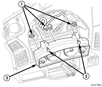
1. Disconnect and isolate the battery negative cable.
2. Remove the cluster bezel from the instrument panel. (Refer to 23 - BODY/INSTRUMENT PANEL/CLUSTER BEZEL - REMOVAL).
3. Remove the two screws (2) that secure the instrument cluster (3) to the instrument panel structural support.
4. Pull the top of the instrument cluster rearward far enough to access and disconnect the instrument panel wire harness connectors (1) from the connector receptacles on the back of the cluster housing.
5. Lift the instrument cluster upward far enough to disengage the two mounting posts on the bottom of the cluster housing from the instrument panel structural support.
6. Remove the instrument cluster from the instrument panel.
DISASSEMBLY
WARNING: To avoid personal injury or death, on vehicles equipped with airbags, disable the supplemental restraint system before attempting any steering wheel, steering column, airbag, seat belt tensioner, impact sensor, or instrument panel component diagnosis or service. Disconnect and isolate the battery negative (ground) cable, then wait two minutes for the system capacitor to discharge before performing further diagnosis or service. This is the only sure way to disable the supplemental restraint system. Failure to take the proper precautions could result in accidental airbag deployment.
NOTE: The cluster lens, hood and mask unit is the only component of the instrument cluster used in this vehicle that is serviced separately. Following is the procedure for disassembling this component from the instrument cluster.
CLUSTER LENS, HOOD, AND MASK
1. Disconnect and isolate the battery negative cable.
2. Remove the instrument cluster from the instrument panel. (Refer to 8 - ELECTRICAL/INSTRUMENT CLUSTER - REMOVAL).
3. Work around the perimeter of the cluster housing to disengage each of the latches that secure the cluster lens, hood, and mask unit (3) to the cluster housing (5).
4. Remove the lens, hood, and mask unit from the face of the instrument cluster.
ASSEMBLY
WARNING: To avoid personal injury or death, on vehicles equipped with airbags, disable the supplemental restraint system before attempting any steering wheel, steering column, airbag, seat belt tensioner, impact sensor, or instrument panel component diagnosis or service. Disconnect and isolate the battery negative (ground) cable, then wait two minutes for the system capacitor to discharge before performing further diagnosis or service. This is the only sure way to disable the supplemental restraint system. Failure to take the proper precautions could result in accidental airbag deployment.
NOTE: The cluster lens, hood and mask unit is the only component of the instrument cluster used in this vehicle that is serviced separately. Following is the procedure for assembling this component to the instrument cluster.
CLUSTER LENS, HOOD, AND MASK
1. Position the cluster lens, hood, and mask unit (3) over the face of the instrument cluster (5).
2. Press firmly and evenly on the lens, hood, and mask unit until each of the latches is fully engaged around the perimeter of the cluster housing.
3. Reinstall the instrument cluster into the instrument panel. (Refer to 8 - ELECTRICAL/INSTRUMENT CLUSTER - INSTALLATION).
4. Reconnect the battery negative cable.
INSTALLATION
WARNING: To avoid personal injury or death, on vehicles equipped with airbags, disable the supplemental restraint system before attempting any steering wheel, steering column, airbag, seat belt tensioner, impact sensor, or instrument panel component diagnosis or service. Disconnect and isolate the battery negative (ground) cable, then wait two minutes for the system capacitor to discharge before performing further diagnosis or service. This is the only sure way to disable the supplemental restraint system. Failure to take the proper precautions could result in accidental airbag deployment.
1. Position the instrument cluster (3) close enough to the instrument panel to reconnect the instrument panel wire harness connectors (1) to the connector receptacles on the back of the cluster housing.
2. Align and insert the two mounting posts on the bottom of the cluster housing into the locator holes in the instrument panel structural support.
3. Tilt the top of the instrument cluster forward until the two upper mounting tabs are positioned to the mounting holes in the instrument panel structural support.
4. Install and tighten the two screws that secure the upper mounting tabs of the instrument cluster. Tighten the screws to 2 N·m (17 in. lbs.).
5. Reinstall the cluster bezel onto the instrument panel. (Refer to 23 - BODY/INSTRUMENT PANEL/CLUSTER BEZEL - INSTALLATION).
6. Reconnect the battery negative cable.
NOTE: Certain indicators in this instrument cluster are automatically configured. This feature allows those indicators to be activated or deactivated for compatibility with certain optional equipment. If a problem is noted that involves improper illumination of an indicator, disconnect and isolate the battery negative cable. After about five minutes, reconnect the battery negative cable and turn the ignition switch to the ON position. The instrument cluster should automatically relearn the equipment in the vehicle and properly configure the configurable indicators accordingly.