MODULE-FRONT CONTROL
DESCRIPTION
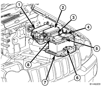
CAUTION: Do not exchange the Front Control Module with the module from another vehicle. Multiple vehicle module configurations may be altered. Use only approved service parts when replacing the module or exchanging the module for diagnostic purposes.
The Front Control Module (FCM) (3) is a micro controller based module located in the left front corner of the engine compartment. The FCM mates directly to the Integrated Power Module (IPM)(2). The IPM connects directly to the battery and provides the primary means of circuit protection and power distribution for many of the vehicle electrical systems. The FCM controls power to some of these vehicle systems electrical and electromechanical loads based on inputs received from hard wired switch inputs and data received on the Controller Area Network (CAN) data bus circuit.
OPERATION
As messages are sent over the Controller Area Network (CAN) bus circuit, the Front Control Module (FCM) reads these messages and controls power to some of the vehicles electrical systems by completing the circuit to ground (low side driver) or completing the circuit to 12 volt power (high side driver). The following functions are controlled by the FCM:
- Front turn signals
- Turn signal and tail lamps
- Front and rear hazard warning lamps
- Headlamps
- Fog Lamps
- Daytime running lamps - if equipped
- Horn
- Windshield wiper and washer systems
- Trailer tow wiring output
- Power Accessory Delay
- Smart Power Accessory Delay
- Manual adjustable pedals
- Hydraulic cooling fan
- Sensor monitoring (ambient, battery voltage, brake pedal position, and hood ajar - if equipped)
The FCM provides the following features for the above function:
- It flashes lamps in response to turn signal, Remote Keyless Entry and Vehicle Theft Security Alarm inputs, (Refer to 8 - ELECTRICAL/OVERHEAD CONSOLE/ELECTRONIC VEHICLE INFO CENTER - OPERATION) for additional information on customer programmable features.
- It sounds the horn in response to Remote Keyless Entry and Vehicle Theft Security Alarm inputs, (Refer to 8 - ELECTRICAL/OVERHEAD CONSOLE/ELECTRONIC VEHICLE INFO CENTER - OPERATION) for additional information on customer programmable features.
- It turns off the horn in the event of excessively long operation that could otherwise damage the horn.
- It minimized voltage variations to the headlamps to extend bulb life.
- If the headlamps are left on, it automatically turns them off after eight minutes to protect the battery from discharge.
- It operates the high-beam headlamps at reduced intensity by pulse-width modulation of the power supply to provide the daytime running lamps.
- It provides the variable delay intermittent windshield wiper feature and the vehicle speed sensitive windshield wiper delay variation.
- It acts as a gateway between the CAN-C network for critical powertrain and anti-lock brake systems and the CAN-B network for body and interior modules as well as the CAN-D network. For example it collects ambient temperature data and relays it to the PCM.
REMOVAL
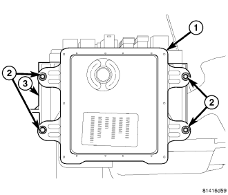
CAUTION: Front Control Module (FCM) damage may occur if the module case comes in contact with the battery while still connected. Always disconnect the battery negative cable prior to removal of the FCM.
1. Disconnect and isolate the battery negative cable.
2. Remove the Integrated Power Module (IPM) from the engine compartment, (Refer to 8 - ELECTRICAL/POWER DISTRIBUTION/INTEGRATED POWER MODULE - REMOVAL).
3. Remove the four fasteners (2) securing the Front Control Module (FCM) (1) to the IPM (3).
4. Separate the FCM from the IPM by pulling the two straight away from each other to disengage the electrical connector.
INSTALLATION
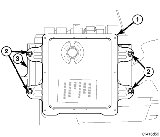
NOTE: If installing a new service part, remove the plastic cover from the original module and install it on the new one.
1. Connect the Integrated Power Module (IPM) (3) to the Front Control Module (FCM) (1) by lining up the electrical connector and pushing the two together.
2. Install the four fasteners (2) securing the FCM (1) to the IPM (3).
3. Install the IPM, (Refer to 8 - ELECTRICAL/POWER DISTRIBUTION/INTEGRATED POWER MODULE - INSTALLATION).
4. Connect the battery negative cable.