MODULE-INTEGRATED POWER
DESCRIPTION
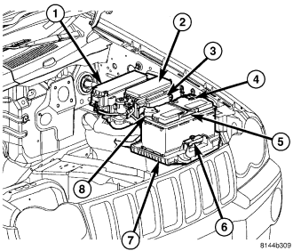
The Integrated Power Module (IPM) (2) is a combination of a printed circuit board based module that contains fuses and relays and the Front Control Module (FCM) (3). The FCM contains electronics that control the IPM as well as other vehicle functions. The IPM connects directly to the battery positive via a stud located on top of the unit. The ground connection is via electrical connectors. The IPM provides the primary means of voltage distribution and protection for many vehicle systems.
The IPM (2) is located in the engine compartment, next to the battery (5) and in front of the Power Distribution Center (PDC) (1). It is secured to a bracket with three locating slots that snap onto the bracket tabs holding it securely in place. The printed circuit board portion of the IPM cannot be repaired and must be replaced if inoperative or damaged, (Refer to 8 - ELECTRICAL/POWER DISTRIBUTION/INTEGRATED POWER MODULE - REMOVAL).
OPERATION
All of the current from the battery and the generator output enters the integrated power module via a stud on the top of the module. Internal connections of all of the power distribution center circuits is accomplished by a combination of bus bars and a printed circuit board.
REMOVAL
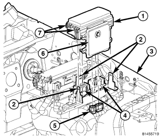
1. Disconnect and isolate the battery negative cable.
2. Remove the Integrated Power Module (IPM) cover by pulling up on the cover tabs (7) and pivoting the cover outward.
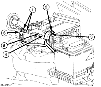
3. Remove the nut (2) from the IPM B+ terminal stud.
4. Remove the battery positive cable (3) from the IPM B+ terminal stud.
5. Using a suitable flat bladed tool, depress the three retaining clips and lift the IPM (1) straight up off of the bracket tabs (2).
6. Disconnect the two IPM connectors (4).
7. Disconnect the two Front Control Module (FCM) connectors (5).
8. Remove the IPM assembly from the vehicle.
INSTALLATION
NOTE: If replacing the Integrated Power Module (IPM) (1) with a new assembly it will be necessary to transfer the circuit protection devices as well as the Front Control Module to the new IPM.
1. Position the IPM into the vehicle.
2. Connect the two Front Control Module (FCM) connectors (5).
3. Connect the two IPM connectors (4).
4. Position the IPM over the three bracket tabs (2) and apply downward pressure until the retaining clips snap into place securely.
5. Install the battery positive cable (3) to the IPM B+ terminal stud.
6. Install the nut (2) to the IPM B+ terminal stud. Tighten the nut to 11.5 N·m (105 in. lbs.).
7. Close the IPM cover ensuring the locking tabs snap firmly in place.
8. Connect the battery negative cable.