MANIFOLD-INTAKE
DESCRIPTION
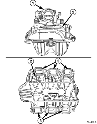
The intake manifold (2) is made of a composite material and features 300 mm (11.811 in.) long runners which maximizes low end torque. The intake manifold (2) uses single plane sealing which consist of six individual press in place port gaskets to prevent leaks. The throttle body (1) attaches directly to the intake manifold (2). Eight studs and two bolts are used to fasten the intake to the head.
REMOVAL
1. Perform the Fuel System Pressure Release procedure (Refer to 14 - FUEL SYSTEM/FUEL DELIVERY - STANDARD PROCEDURE).
2. Disconnect negative cable from battery.
3. Remove resonator assembly and air inlet hose.
4. Disconnect throttle and speed control cables.
5. Disconnect electrical connectors for the following components: Refer to FUEL SYSTEM for component locations.
- Manifold Absolute Pressure (MAP) Sensor
- Intake Air Temperature (IAT) Sensor
- Throttle Position (TPS) Sensor
- Coolant Temperature (CTS) Sensor
- Idle Air Control (IAC) Motor
6. Disconnect vapor purge hose, brake booster hose, speed control servo hose, positive crankcase ventilation (PCV) hose.
7. Remove the generator.
8. Remove the air conditioning compressor.
9. Disconnect left and right radio suppressor straps.
10. Disconnect and remove ignition coil towers.
11. Remove top oil dipstick tube retaining bolt and ground strap.
12. Remove fuel rail.
13. Remove throttle body assembly and mounting bracket.
14. Drain cooling system below coolant temperature level (Refer to 7 - COOLING - STANDARD PROCEDURE) .
15. Remove the heater hoses from the engine front cover and the heater core.
16. Unclip and remove heater hoses and tubes from intake manifold.
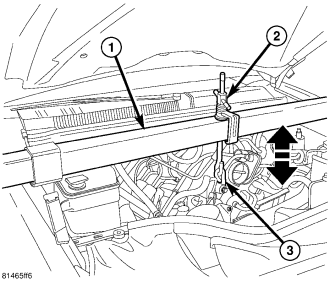
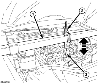
17. Support engine using engine support fixture (1), special tool # 8534.
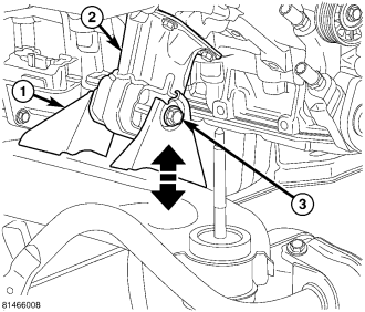
18. Remove the right side engine mount to frame bolt (3).
19. With the bolt removed, lower engine until engine mount rests in frame mount.
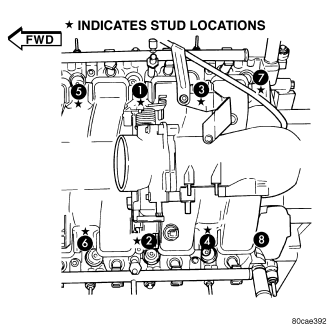
20. Remove intake manifold retaining fasteners in reverse order of tightening sequence.
21. Remove intake manifold.
INSTALLATION
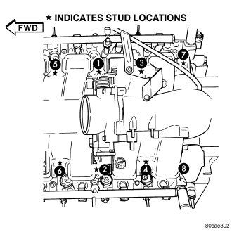
1. Install intake manifold gaskets.
2. Install intake manifold.
3. Install intake manifold retaining bolts and tighten in sequence shown in to 12 N·m (105 in. lbs.).
4. Install left and right radio suppressor straps.
5. Install throttle body assembly.
6. Connect throttle cable and speed control cable to throttle body.
7. Install fuel rail.
8. Install ignition coil towers.
9. Position and install heater hoses and tubes onto intake manifold.
10. Install the heater hoses to the heater core and engine front cover.
11. Connect electrical connectors for the following components:
- Manifold Absolute Pressure (MAP) Sensor
- Intake Air Temperature (IAT) Sensor
- Throttle Position (TPS) Sensor
- Coolant Temperature (CTS) Sensor
- Idle Air Control (IAC) Motor
- Ignition coil towers
- Fuel injectors
12. Install top oil dipstick tube retaining bolt and ground strap.
13. Install generator.
14. Install the air conditioning compressor.
15. Connect Vapor purge hose, Brake booster hose, Speed control servo hose, Positive crankcase ventilation (PCV) hose.
16. Fill cooling system (Refer to 7 - COOLING - STANDARD PROCEDURE).
17. Raise engine using engine support fixture (1), special tool # 8534.
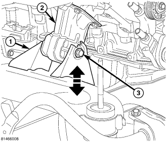
18. Install the right side engine mount to frame bolt (3).
19. Remove engine support fixture, special tool # 8534.
20. Install resonator assembly and air inlet hose.
21. Connect negative cable to battery.