CYLINDER HEAD - LEFT
REMOVAL - LEFT CYLINDER HEAD
1. Disconnect the negative cable from the battery.
2. Raise the vehicle on a hoist.
3. Disconnect the exhaust pipe at the left side exhaust manifold.
4. Drain the engine coolant. Refer to COOLING SYSTEM.
5. Lower the vehicle.
6. Remove the intake manifold (Refer to 9 - ENGINE/MANIFOLDS/INTAKE MANIFOLD - REMOVAL).
7. Remove the master cylinder and booster assembly. Refer to section 5 brakes.
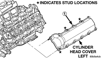
8. Remove the cylinder head cover (Refer to 9 - ENGINE/CYLINDER HEAD/CYLINDER HEAD COVER(S) - REMOVAL).
9. Remove the fan shroud and fan blade assembly (Refer to 7 - COOLING/ENGINE/FAN DRIVE VISCOUS CLUTCH - REMOVAL).
10. Remove accessory drive belt (Refer to 7 - COOLING/ACCESSORY DRIVE/DRIVE BELTS - REMOVAL).
11. Remove the power steering pump and set aside.
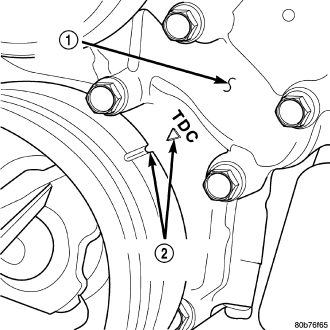
12. Rotate the crankshaft until the damper timing mark is aligned with TDC indicator mark.
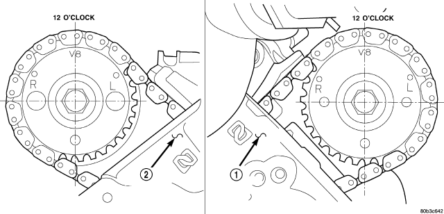
13. Verify the V8 mark on the camshaft sprocket is at the 12 o'clock position. Rotate the crankshaft one turn if necessary.
14. Remove the crankshaft damper (Refer to 9 - ENGINE/ENGINE BLOCK/VIBRATION DAMPER - REMOVAL).
15. Remove the timing chain cover (Refer to 9 - ENGINE/VALVE TIMING/TIMING BELT / CHAIN COVER(S) - REMOVAL).
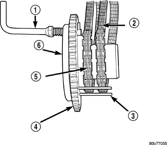
16. Lock the secondary timing chains to the idler sprocket using Special Tool 8429.
NOTE: Mark the secondary timing chain prior to removal to aid in installation.
17. Mark the secondary timing chain, one link on each side of the V8 mark on the camshaft drive gear.
18. Remove the left side secondary chain tensioner (Refer to 9 - ENGINE/VALVE TIMING/TIMING BELT/CHAIN AND SPROCKETS - REMOVAL).
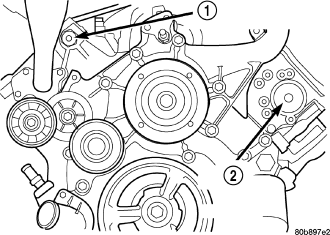
19. Remove the cylinder head access plug (2).
20. Remove the left side secondary chain guide (Refer to 9 - ENGINE/VALVE TIMING/TIMING BELT/CHAIN AND SPROCKETS - REMOVAL).
21. Remove the retaining bolt and the camshaft drive gear.
CAUTION: Do not allow the engine to rotate. Severe damage to the valve train can occur.
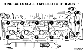
CAUTION: Do not overlook the four smaller bolts at the front of the cylinder head. Do not attempt to remove the cylinder head without removing these four bolts.
NOTE: The cylinder head is attached to the cylinder block with fourteen bolts.
22. Remove the cylinder head retaining bolts using the sequence provided.
23. Remove the cylinder head and gasket. Discard the gasket.
CAUTION: Do not lay the cylinder head on its gasket sealing surface, due to the design of the cylinder head gasket any distortion to the cylinder head sealing surface may prevent the gasket from properly sealing resulting in leaks.
CLEANING
To ensure engine gasket sealing, proper surface preparation must be performed, especially with the use of aluminum engine components. (Refer to 9 - ENGINE - STANDARD PROCEDURE)
INSPECTION
1. Inspect the cylinder head for out-of-flatness, using a straightedge and a feeler gauge. If tolerances exceed 0.0508 mm (0.002 in.) replace the cylinder head.
2. Inspect the valve seats for damage. Service the valve seats as necessary.
3. Inspect the valve guides for wear, cracks or looseness. If either condition exist, replace the cylinder head.
INSTALLATION - LEFT CYLINDER HEAD
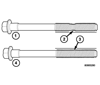
NOTE: The cylinder head bolts are tightened using a torque plus angle procedure. The bolts must be examined BEFORE reuse. If the threads are necked down (2) the bolts should be replaced.
Necking can be checked by holding a straight edge against the threads. If all the threads do not contact the scale, the bolt should be replaced.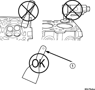
CAUTION: When cleaning cylinder head and cylinder block surfaces, DO NOT use a metal scraper because the surfaces could be cut or ground. Use only a wooden or plastic scraper (1).
1. Clean the cylinder head and cylinder block mating surfaces.
2. Position the new cylinder head gasket on the locating dowels.
CAUTION: When installing cylinder head, use care not damage the tensioner arm or the guide arm.
3. Position the cylinder head onto the cylinder block. Make sure the cylinder head seats fully over the locating dowels.
NOTE: The four smaller cylinder head mounting bolts require sealant to be added to them before installing. Failure to do so may cause leaks.
4. Lubricate the cylinder head bolt threads with clean engine oil and install the ten M11 bolts.
5. Coat the four M8 cylinder head bolts with Mopar® Lock and Seal Adhesive then install the bolts.
NOTE: The cylinder head bolts are tightened using an angle torque procedure, however, the bolts are not a torque-to-yield design.
6. Tighten the bolts in sequence using the following steps and torque values:
- Step 1: Tighten bolts 1–10, 20 N·m (15 ft. lbs.).
- Step 2: Tighten bolts 1–10, 47 N·m (35 ft. lbs.). Tighten bolts 11–14, 25 N·m (18 ft. lbs.).
- Step 3: Tighten bolts 1–10, 90 degrees. Tighten bolts 11–14, 30 N·m (22 ft. lbs.).
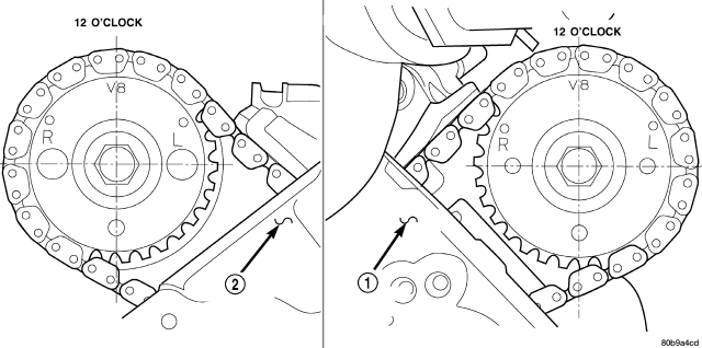
7. Position the secondary chain onto the camshaft drive gear, making sure one marked chain link is on either side of the V8 mark on the gear and position the gear onto the camshaft.
8. Install the camshaft drive gear retaining bolt.
9. Install the left side secondary chain guide (Refer to 9 - ENGINE/VALVE TIMING/TIMING BELT/CHAIN AND SPROCKETS - INSTALLATION).
10. Install the cylinder head access plug (2).
11. Re-set and Install the left side secondary chain tensioner (Refer to 9 - ENGINE/VALVE TIMING/TIMING BELT/CHAIN AND SPROCKETS - INSTALLATION).
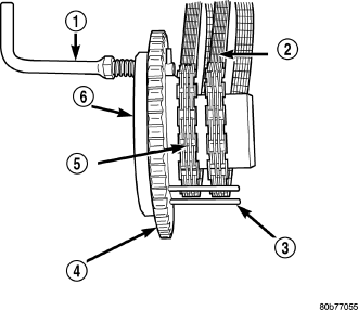
12. Remove Special Tool 8429 (6).
13. Install the timing chain cover (Refer to 9 - ENGINE/VALVE TIMING/TIMING BELT / CHAIN COVER(S) - INSTALLATION).
14. Install the crankshaft damper (Refer to 9 - ENGINE/ENGINE BLOCK/VIBRATION DAMPER - INSTALLATION).
15. Install the power steering pump.
16. Install the fan blade assembly and fan shroud (Refer to 7 - COOLING/ENGINE/FAN DRIVE VISCOUS CLUTCH - INSTALLATION).
17. Install the cylinder head cover (Refer to 9 - ENGINE/CYLINDER HEAD/CYLINDER HEAD COVER(S) - INSTALLATION).
18. Reinstall the master cylinder and booster assembly. Refer to section 5 brakes.
19. Install the intake manifold (Refer to 9 - ENGINE/MANIFOLDS/INTAKE MANIFOLD - INSTALLATION).
20. Refill the cooling system (Refer to 7 - COOLING - STANDARD PROCEDURE).
21. Raise the vehicle.
22. Install the exhaust pipe onto the left exhaust manifold.
23. Lower the vehicle.
24. Connect the negative cable to the battery.
25. Start the engine and check for leaks.