MANIFOLD - INTAKE
- DESCRIPTION
- DIAGNOSIS AND TESTING - INTAKE MANIFOLD LEAKAGE
- REMOVAL
- CLEANING
- INSPECTION
- INSTALLATION
DESCRIPTION
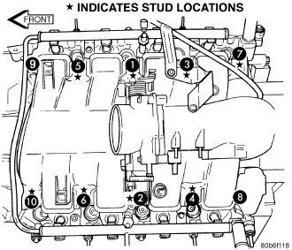
The intake manifold is made of a composite material and features long runners which maximizes low end torque. The intake manifold uses single plane sealing which consist of eight individual press in place port gaskets to prevent leaks. Eight studs and two bolts are used to fasten the intake to the head.
DIAGNOSIS AND TESTING - INTAKE MANIFOLD LEAKAGE
An intake manifold air leak is characterized by lower than normal manifold vacuum. Also, one or more cylinders may not be functioning.
WARNING: USE EXTREME CAUTION WHEN THE ENGINE IS OPERATING. DO NOT STAND IN A DIRECT LINE WITH THE FAN. DO NOT PUT YOUR HANDS NEAR THE PULLEYS, BELTS OR THE FAN. DO NOT WEAR LOOSE CLOTHING.
1. Start the engine.
2. Spray a small stream of water at the suspected leak area.
3. If a change in RPM is observed the area of the suspected leak has been found.
4. Repair as required.
REMOVAL
1. Perform the Fuel System Pressure Release procedure (Refer to 14 - FUEL SYSTEM/FUEL DELIVERY - STANDARD PROCEDURE).
2. Disconnect negative cable from battery.
3. Remove air cleaner housing and throttle body resonator.
4. Disconnect throttle and speed control cables.
5. Disconnect electrical connectors for the following components:
- Manifold Absolute Pressure (MAP) Sensor
- Intake Air Temperature (IAT) Sensor
- Throttle Position (TPS) Sensor
- Coolant Temperature (CTS) Sensor
- Idle Air Control (IAC) Motor
6. Disconnect vapor purge hose, brake booster hose, speed control servo hose, positive crankcase ventilation (PCV) hose.
7. Remove accessory drive belt (Refer to 7 - COOLING/ACCESSORY DRIVE/DRIVE BELTS - REMOVAL).
8. Disconnect generator electrical connections.
9. Unbolt the generator and move it away from the intake manifold for clearance.
10. Disconnect air conditioning compressor electrical connections.
11. Unbolt the air conditioning compressor and move it away from the intake manifold for clearance.
12. Disconnect left and right radio suppressor straps.
13. Disconnect and remove ignition coil towers (Refer to 8 - ELECTRICAL/IGNITION CONTROL/IGNITION COIL - REMOVAL).
14. Remove top oil dipstick tube retaining bolt and ground strap.
15. Remove fuel rail (Refer to 14 - FUEL SYSTEM/FUEL DELIVERY/FUEL RAIL - REMOVAL).
16. Remove throttle body assembly and mounting bracket.
17. Drain cooling system below coolant temperature level (Refer to 7 - COOLING - STANDARD PROCEDURE).
18. Remove intake manifold retaining fasteners, in reverse order of tightening sequence .
NOTE: Intake must be lifted upward and level in the front and rear to clear the cowl. Interference with the cowl will occur during removal.
19. Remove intake manifold.
CLEANING
NOTE: There is NO approved repair procedure for the intake manifold. If severe damage is found during inspection, the intake manifold must be replaced.
Before installing the intake manifold thoroughly clean the mating surfaces. Use a suitable cleaning solvent, then air dry.
INSPECTION
1. Inspect the intake sealing surface for cracks, nicks and distortion.
2. Inspect the intake manifold vacuum hose fittings for looseness or blockage.
3. Inspect the manifold to throttle body mating surface for cracks, nicks and distortion.
INSTALLATION
1. Install intake manifold gaskets.
2. Install intake manifold.
3. Install intake manifold retaining bolts and tighten in sequence shown in to 12 N·m (105 in. lbs.).
4. Install left and right radio suppressor straps.
5. Install throttle body assembly.
6. Install throttle cable bracket.
7. Connect throttle cable and speed control cable to throttle body.
8. Install fuel rail (Refer to 14 - FUEL SYSTEM/FUEL DELIVERY/FUEL RAIL - INSTALLATION).
9. Install ignition coil towers (Refer to 8 - ELECTRICAL/IGNITION CONTROL/IGNITION COIL - INSTALLATION).
10. Install coolant temperature sensor (Refer to 7 - COOLING/ENGINE/ENGINE COOLANT TEMP SENSOR - INSTALLATION).
11. Connect electrical connectors for the following components:
- Manifold Absolute Pressure (MAP) Sensor
- Intake Air Temperature (IAT) Sensor
- Throttle Position (TPS) Sensor
- Coolant Temperature (CTS) Sensor
- Idle Air Control (IAC) Motor
- Ignition coil towers
- Fuel injectors
12. Install top oil dipstick tube retaining bolt and ground strap.
13. Install generator including electrical connections (Refer to 8 - ELECTRICAL/CHARGING/GENERATOR - INSTALLATION).
14. Connect Vapor purge hose, Brake booster hose, Speed control servo hose, Positive crankcase ventilation (PCV) hose.
15. Install air conditioning compressor including electrical connections.
16. Fill cooling system (Refer to 7 - COOLING - STANDARD PROCEDURE).
17. Install accessory drive belt (Refer to 7 - COOLING/ACCESSORY DRIVE/DRIVE BELTS - INSTALLATION).
18. Install air cleaner housing and throttle body resonator. Tighten resonator bolts 5 N·m (44 in. lbs.).
19. Connect negative cable to battery.