MANIFOLD - INTAKE
- DESCRIPTION
- DIAGNOSIS AND TESTING - INTAKE MANIFOLD LEAKAGE
- REMOVAL
- CLEANING
- INSPECTION
- INSTALLATION
DESCRIPTION
The intake manifold is made of aluminum, and features runners to maximize power. The intake manifold uses single plane sealing which consist of two edge molded gaskets to prevent leaks.
DIAGNOSIS AND TESTING - INTAKE MANIFOLD LEAKAGE
An intake manifold air leak is characterized by lower than normal manifold vacuum. Also, one or more cylinders may not be functioning.
WARNING: USE EXTREME CAUTION WHEN THE ENGINE IS OPERATING. DO NOT STAND IN A DIRECT LINE WITH THE FAN. DO NOT PUT YOUR HANDS NEAR THE PULLEYS, BELTS OR THE FAN. DO NOT WEAR LOOSE CLOTHING.
1. Start the engine.
2. Spray a small stream of water at the suspected leak area.
3. If a change in RPM is observed the area of the suspected leak has been found.
4. Repair as required.
REMOVAL
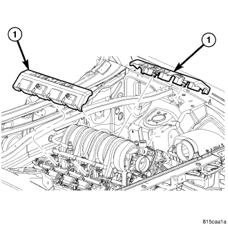
1. Remove engine covers (1).
2. Bleed fuel system (Refer to 14 - FUEL SYSTEM/FUEL DELIVERY - STANDARD PROCEDURE).
3. Disconnect negative cable from battery.
4. Remove air inlet hose.
5. Disconnect electrical connectors for the following components:
- Manifold Absolute Pressure (MAP) Sensor
- Fuel Injectors
- ETC ( Electric Throttle Control )
6. Disconnect brake booster hose, purge hose, and MUA hose ( Make Up Air Hose ).
7. Remove intake manifold retaining fasteners in a crisscross pattern starting from the outside bolts and ending at the middle bolts.
8. Remove intake manifold as an assembly.
CLEANING
NOTE: There is NO approved repair procedure for the intake manifold. If severe damage is found during inspection, the intake manifold must be replaced.
Before installing the intake manifold thoroughly clean the mating surfaces. Use a suitable cleaning solvent, then air dry.
INSPECTION
1. Inspect the intake sealing surface for cracks, nicks and distortion.
2. Inspect the intake manifold vacuum hose fittings for looseness or blockage.
INSTALLATION
1. Position intake manifold.
2. Install intake manifold retaining bolts, and tighten in sequence from the middle bolts towards the outside in a crisscross pattern. Torque fasteners to 124 N·m (124 in. lbs.).
3. Connect electrical connectors for the following components:
- Manifold Absolute Pressure (MAP) Sensor
- Fuel Injectors
- ETC ( Electronic Throttle Control )
4. Connect Brake booster hose, purge hose, and MUA hose ( Make Up Air hose ).
5. Install air inlet hose.
6. Connect negative cable to battery.
7. Install engine covers (1).