MODULE-TRAILER TOW
DESCRIPTION
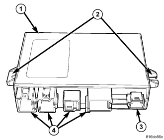
The Trailer Module (TM) (1) is used only on vehicles manufactured for certain export markets and equipped with a factory-installed trailer towing package. The TM is secured on a molded plastic tray-like mounting plate located on the rear floor panel near the transmission tunnel under the right rear seat cushion. The module is connected to the vehicle electrical system through dedicated take outs and connectors of the body wire harness.
There are two mounting tabs (2) integral to the TM housing that secure the module through two latch features integral to the mounting plate. Four connector receptacles (4) containing terminal pins that connect the module to the vehicle electrical system are integral to the one side of the housing. One additional receptacle (3) is not utilized in this application.
The TM cannot be adjusted or repaired and, if damaged or ineffective, it must be replaced.
OPERATION
The microprocessor within the Trailer Module (TM) contains the trailer tow lighting and electrical control logic circuits. The module uses On-Board Diagnostics (OBD) and can communicate with other electronic modules in the vehicle as well as with the diagnostic scan tool using the Controller Area Network (CAN) data bus. This method of communication is also used for trailer tow lighting and electrical control system diagnosis and testing through the 16-way data link connector located on the driver side lower edge of the instrument panel.
Pre-programmed decision algorithms allow the TM microprocessor to determine the appropriate trailer tow electrical control outputs based upon hard wired inputs from the brake lamp switch and the ignition switch as well as from electronic message inputs received from the Front Control Module (FCM) over the CAN data bus. When the programmed conditions are met, the TM provides voltage to the appropriate trailer tow lighting and electrical control circuits. These circuits feed the trailer circuits through dedicated trailer tow wiring in the vehicle and the trailer tow connector on the trailer hitch platform.
The TM also continuously monitors the resistance through each of these electrical output circuits, which allows the module logic circuits to detect problems and determine the system readiness. If the module detects a monitored system fault, it sets a Diagnostic Trouble Code (DTC) and sends the appropriate electronic messages to the FCM over the CAN data bus. The FCM responds to these messages by increasing the flash rate of the turn signal circuits and transmitting electronic messages to the ElectroMechanical Instrument Cluster (EMIC) (also known as the Cab Compartment Node/CCN. The EMIC then provides feedback to the vehicle operator by increasing the flash rate of the turn signal indicators and increasing the click rate of a solid state relay that emulates the audible output of an electromechanical turn signal flasher.
The TM receives battery current on a fused B(+) circuit and a fused ignition switch output (run-start) circuit through fuses in the Junction Block (JB). The module receives ground through a ground circuit and take out of the body wire harness. These connections allow the module to be operational regardless of the ignition switch position.
The hard wired inputs and outputs of the TM may be diagnosed using conventional diagnostic tools and procedures. Refer to the appropriate wiring information. However, conventional diagnostic methods will not prove conclusive in the diagnosis of the TM or the electronic controls or communication between modules and other devices that provide some features of the trailer tow lighting system. The most reliable, efficient, and accurate means to diagnose the TM or the electronic controls and communication related to TM operation requires the use of a diagnostic scan tool. Refer to the appropriate diagnostic information.
REMOVAL
1. Disconnect and isolate the battery negative cable.
2. Remove the rear seat cushion from the rear floor panel. (Refer to 23 - BODY/SEATS/CUSHION-REAR SEAT - REMOVAL).
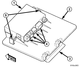
3. Disconnect the four body wire harness connectors from the connector receptacles (4) on the back of the Trailer Module (TM) (1).
4. Using a trim stick or another suitable wide flat-bladed tool, gently pry the latch features (5) on each side of the mounting plate (2) away from the mounting tabs of the module far enough to disengage the module.
5. Remove the module from the mounting plate.
INSTALLATION
1. Position the Trailer Module (TM) (1) to the mounting plate (2) and insert the two mounting tabs on the sides of the module into the latch feature (5) cavities in the plate.
2. Push downward on the module until the two latch features integral to the mounting plate are fully engaged over the mounting tabs on the sides of the module.
3. Reconnect the four body wire harness connectors to the module connector receptacles (4).
4. Reinstall the rear seat cushion onto the rear floor panel. (Refer to 23 - BODY/SEATS/CUSHION-REAR SEAT - INSTALLATION).
5. Reconnect the battery negative cable.