JUNCTION BLOCK
DESCRIPTION
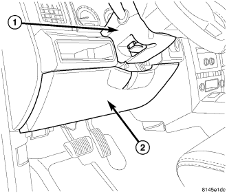
An electrical Junction Block (JB) is concealed beneath the driver side of the instrument panel in the passenger compartment of the vehicle. The JB is accessed by pulling down on the steering column opening cover (2) exposing the lower steering column and portions of the instrument panel wiring harness. The JB combines the functions previously provided by a separate fuseblock module and relay center. The JB serves to simplify and centralize numerous electrical components, as well as to distribute electrical current to many of the accessory systems in the vehicle. It also eliminates the need for numerous splice connections. The JB houses blade-type mini fuses, blade-type automatic resetting circuit breakers and International Standards Organization (ISO) relays.
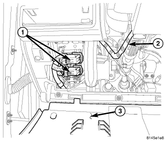
The molded plastic JB housing is secured with four screws and two snap retainers to the JB mounting bracket behind the instrument panel steering column opening cover (3). The steering column opening cover can be pulled downward to disengage the latches and provide service access to all of the fuses, relays and wire harness connectors (1) of the JB. Refer to Steering Column Opening Cover in Body for additional service information.
The JB contains six relays that are integral to the housing assembly. The relays cannot be replaced separately. If any of the relays are diagnosed inoperative or damaged the complete JB unit must be replaced. The six relays are:
- Lock relay
- Unlock relay
- Driver door unlock relay
- Rear wiper relay
- Ignition “RUN” relay
- Ignition “RUN/ACCESSORY DELAY” relay
The JB unit cannot be repaired and is only serviced as an assembly. If any internal circuit or the JB housing is inoperative or damaged, the entire JB unit must be replaced, (Refer to 8 - ELECTRICAL/POWER DISTRIBUTION/JUNCTION BLOCK - REMOVAL) for the appropriate procedure.
OPERATION
All of the circuits entering and leaving the Junction Block (JB) do so through three wire harness connectors, which are connected to the JB through integral connector receptacles molded into the JB housing. Internal connection of all of the JB circuits is accomplished by a printed circuit board. Refer to the appropriate wiring information for complete circuit diagrams. The wiring information includes wiring diagrams, proper wire and connector repair procedures, details of wire harness routing and retention, connector pin-out information and location views for the various wire harness connectors, splices and grounds.
REMOVAL
WARNING: Disable the airbag system before attempting any steering wheel, steering column, or instrument panel component diagnosis or service. Disconnect and isolate the battery negative (ground) cable, then wait two minutes for the airbag system capacitor to discharge before performing further diagnosis or service. This is the only sure way to disable the airbag system. Failure to take the proper precautions could result in accidental airbag deployment and possible personal injury.
1. Disconnect and isolate the battery negative cable.
2. Remove the steering column opening cover (2). This is accomplished by pulling outward on the upper edge of the cover to disengage the retaining clips and removing the screw at the bottom of the cover.
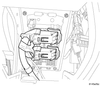
3. Disconnect the two bottom side Junction Block (JB) connectors.
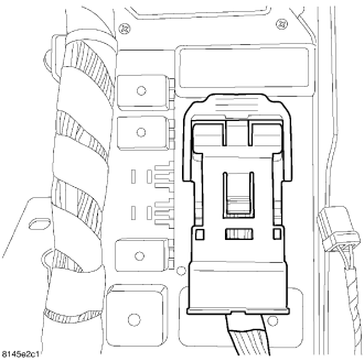
4. Reach behind the JB to disconnect the top side JB connector.
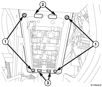
5. Remove the screws (1) that secure the JB to the mounting bracket.
6. Disengage the two snap clips (2) that secure the top of the JB to the mounting bracket. Push the top of the junction block out of the top of the bracket and pull it upward to disengage the lower retaining tabs (3).
7. Remove the JB from the vehicle by lowering out of the opening at the bottom of the instrument panel.
INSTALLATION
NOTE: If the Junction Block (JB) is being replaced with a new unit, be certain to transfer each of the fuses, circuit breakers and relays from the inoperative JB to the proper cavities of the replacement JB. Refer to Junction Block in Wiring Diagrams for the location of complete circuit diagrams and cavity assignments for the JB.
1. Position the JB into its mounting location on the JB mounting bracket.
2. Align the two lower retaining tabs (3) with the slots in the bottom of the bracket.
3. Align the snap clips (2) at the top of the JB with the mounting slots in the top of the bracket.
4. Grasp the JB firmly with both hands and push it into the bracket to engage the two snap clips (2) that secure the top of the JB.
5. Install and tighten the four screws (1) that secure the JB to the mounting bracket. Tighten the screws to 2 N·m (20 in. lbs.).
6. Reconnect the top side wire harness connector to the connector receptacle on the JB.
7. Reconnect the bottom side wire harness connectors to the connector receptacles on the JB.
8. Install the steering column opening cover (2). Install the screw and firmly push the top of the panel inward to engage the top retaining clips.
9. Reconnect the battery negative cable.