STANDARD PROCEDURE
SMARTBEAM® DEMONSTRATION MODE
The SmartBeam® automatic high beam system has a demonstration mode. This mode allows the function of the automatic high beams accompanied with that of the high beam indicator in the instrument cluster to be demonstrated while the vehicle is stationary and under any ambient lighting conditions. Besides demonstrating the automatic high beam system, this mode will confirm that the system electronics and circuitry are functional. This mode also incorporates a feature that allows a functional test of the imager optics to be performed.
NOTE: The SmartBeam® Demonstration Mode will NOT be functional when a diagnostic scan tool is connected to the 16-way Data Link Connector (DLC) beneath the instrument panel on the driver side. Once the demonstration sequence has begun, a detected vehicle speed input of over 8 kilometers-per-hour (5 miles-per-hour) will cause the sequence to be aborted and the automatic high beam system to return to normal operation.
1. Place the headlamp switch in the Automatic (A) position.
2. With the ignition switch in the OFF position, depress and hold depressed the power ON/OFF button (w/o hands-free communication option) or the AUTO button (w/hands-free communication option) on the electrochromic inside rear view mirror.
3. With the button still depressed, start the engine by turning the ignition switch to the START position.
4. Continue to hold the button depressed until the Demonstration Mode begins (headlamp high beams and high beam indicator illuminate), at which time the button may be released.
5. The automatic high beam system will complete three cycles of ramping up the headlamp high beams to full brightness, then ramping them down until fully extinguished accompanied by the appropriate indications from the high beam indicator. At the conclusion of this sequence (about 40 seconds), the automatic high beam system will return to normal operation.
IMAGER OPTICS TEST
If the green Light Emitting Diode (LED) located on the electrochromic inside rear view mirror to the right of the power ON/OFF button (w/o hands-free communication option) or to the left of the AUTO button (w/hands-free communication option) does not flash ON and OFF several times when the ignition switch is turned to the ON position, but the automatic high beam system is not operating as it should, the SmartBeam® imager optics may be dirty or obstructed. The optics of the imager may be tested while the automatic high beam system is in the Demonstration Mode. This test will confirm that the imager can see ambient light through the imager lens and the windshield. If the LED does flash when the ignition switch is turned to the ON position, (Refer to 8 - ELECTRICAL/LAMPS/LIGHTING - EXTERIOR - DIAGNOSIS AND TESTING - SMARTBEAM).
1. Begin by initiating the automatic high beam Demonstration Mode.
2. Observe the green LED located on the electrochromic inside rear view mirror to the right of the power ON/OFF button (w/o hands-free communication option) or to the left of the AUTO button (w/hands-free communication option).
3. Obstruct the view of the imager by placing a hand or another suitable obstruction between the imager lens and the windshield, or over the windshield glass in front of the imager. The LED should extinguish each time the optics are obstructed, then illuminate again each time the obstruction is removed.
4. Failure of the LED to respond to these inputs indicates that the imager optics are obstructed.
CAUTION: Do not spray glass cleaners directly onto the imager lens. Damage to the imager optics and electronics may result.
5. Clean the imager lens and the windshield glass or remove any obstructions from the windshield in front of the imager. To clean the imager lens, spray a small amount of glass cleaner onto a soft cloth and gently wipe the lens clean.
6. Repeat the test to confirm proper automatic high beam imager operation.
IMAGER SHIM ADJUSTMENT
NOTE: The following procedure is used to mechanically adjust the SmartBeam® imager (camera) ONLY after the SmartBeam® Calibration Procedure has resulted in a High Beam Camera Alignment Performance Fault - Left, Right, Top or Bottom Diagnostic Trouble Code (DTC) or a combination of any two of these faults being set. The imager is assembled to a mounting bracket on the inside rear view mirror with four screws. Four stepped plastic shims along with an integral plastic tree that joins the shims are factory assembled between the mounting bracket and the imager at the time of manufacture. A single shim is located at each screw location. The following procedure details the proper steps for repositioning the appropriate shims to correct each fault or combination of faults. However, retrieval and erasure of the DTC to complete and verify the procedure will require the use of a diagnostic scan tool. Refer to the appropriate diagnostic procedures.
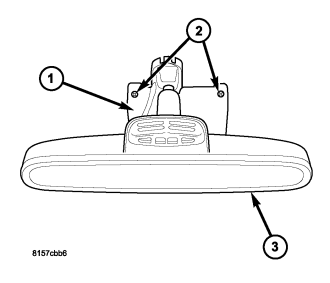
1. Using a diagnostic scan tool, read and record the SmartBeam® (also known as the Automatic High Beam Module/AHBM) Diagnostic Trouble Code (DTC) data. Refer to the appropriate diagnostic procedures.
2. Adjust the inside rear view mirror head (3) downward far enough to access and remove the two screws (2) that secure the rear cover (1) to the imager housing.
3. Adjust the mirror head up toward the headliner to its uppermost position.
4. Unsnap and pull the upper edge of the rear cover away from the imager housing far enough to disengage the tabs at the lower edge of the cover, then remove the cover from the housing.
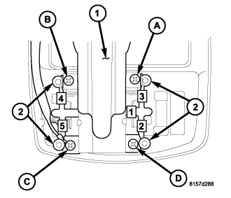
5. Refer to the Imager Adjustment Table that follows for the fault code or codes that have been recorded. Carefully cut the plastic tree for the shims (2) at the appropriate location or locations (boxed numbers in the preceding graphic) for the fault or fault combination.
| IMAGER ADJUSTMENT TABLE | ||
| High Beam Camera Alignment Performance Fault DTC | Shim Tree Cut Location(s) - (Boxed Numbers In Graphic) | Shim Screw Locations - (Circled Letters In Graphic) |
| B16A8 - Right | (1) | (A) and (D) |
| B16A7 - Left | (1) | (B) and (C) |
| B16A9 - Top | (3) and (4) | (A) and (B) |
| B16AA - Bottom | (2) and (5) | (C) and (D) |
| If more than one High Beam Camera Alignment Performance Fault DTC was retrieved, the appropriate screws should be loosened and their shims relocated for both of
the two faults. One screw and one shim will be common to both of the faults. In this case, the total amount of available correction will be slightly diminished from that available for a single fault. However,
in most cases, this action should result in a sufficient amount of correction to remedy both fault conditions. | ||
6. Refer to the Imager Adjustment Table again for the fault code or codes that have been recorded. Locate and loosen one-half turn (counterclockwise) those screws on the rear view mirror bracket (1) at the appropriate locations (circled letters in the preceding graphic) for the fault or fault combination.
7. Slide the shim beneath each of the loosened screws to its most outboard position.
8. Tighten each of the loosened screws to secure the imager and shims to the mirror bracket. Tighten the screws to 0.8 N·m (7 in. lbs.).
9. Engage the tabs at the lower edge of the rear cover to the bottom of the imager housing. Be certain that the imager wiring is held against the mirror bracket, then snap the upper edge of the cover into place on the housing.
10. Install and tighten the two screws that secure the rear cover to the imager housing. Tighten the screws to 0.7 N·m (6 in. lbs.).
11. Use the diagnostic scan tool to erase any SmartBeam DTC data. Refer to the appropriate diagnostic information.
12. The SmartBeam® calibration procedure should be performed following any imager shim adjustment procedure. (Refer to 8 - ELECTRICAL/LAMPS/LIGHTING - EXTERIOR/SMARTBEAM - STANDARD PROCEDURE - SMARTBEAM® CALIBRATION).
SMARTBEAM® CALIBRATION
SmartBeam® calibration must be performed after the inside rear view mirror is replaced with a new unit, and may also be required following any rear view mirror mounting button or windshield replacement procedure. The calibration procedure ensures that the field of vision for the SmartBeam® imager is aimed at the proper path directly ahead of the vehicle. New and unused replacement SmartBeam® units are shipped in calibration mode, which will be indicated by a slow (once-per-second) continuously flashing electrochromic mirror Light Emitting Diode (LED) while the ignition switch is in the ON position. Complaints of poor or improper system performance following mirror mounting button or windshield replacement indicate the need for SmartBeam® calibration.
VEHICLE PREPARATION FOR SMARTBEAM® CALIBRATION
1. Be certain that the imager lens and the windshield glass in front of the imager lens are clean and free from obstructions.
2. Be certain that the inside rear view mirror mounting set screw is tightened to 1.7 N·m (15 in. lbs.).
3. Repair or replace any ineffective, worn or damaged suspension components that could hinder proper SmartBeam® calibration.
4. Verify proper tire inflation pressures.
5. Remove any accumulations of mud, snow or ice from the vehicle underbody.
6. Verify that there is no load in the vehicle (cargo or passengers), except for the driver.
7. The fuel tank should be FULL. Add 2.94 kilograms (6.5 pounds) of weight over the fuel tank for each estimated gallon of missing fuel.
8. Verify correct vehicle suspension height.
9. Verify that the vehicle has at least 16 kilometers (10 miles) showing on the odometer.
MARK IMAGER CENTERLINE ON WINDSHIELD
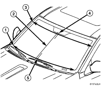
1. Take a measurement (3) across the lower edge of the tint band at the top of the windshield using the shaft of the tint band arrow within the AS1 marking on each side of the glass as the reference points.
2. Divide the upper measurement in half and mark that dimension near the lower edge of the tint band on the glass (4) using a grease pencil. This is the upper centerline of the glass.
3. Take a measurement (1) across the upper edge of the blackout area at the base of the windshield using the inside corner where each side blackout area intersects the lower blackout area as the reference points.
4. Divide the lower measurement in half and mark that dimension near the upper edge of the lower blackout area on the glass (5) using a grease pencil. This is the lower centerline of the glass.
5. Measure and mark 21 millimeters (0.827 inches) toward the passenger side of the windshield from the upper and lower glass centerline marks and draw a line (2) between these marks. This is the centerline of the imager.
NOTE: Be certain to clean the centerline marks from the area of the glass in front of the imager lens before attempting to calibrate the SmartBeam® unit.
MARK IMAGER CENTERLINE ON LIFTGATE GLASS
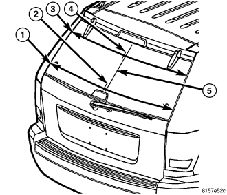
1. Take a measurement (3) across the lower edge of the liftgate glass hinges using the vertical edges of the body liftgate opening as the reference points.
2. Divide the upper measurement in half and mark that dimension on the glass (4) using a grease pencil. This is the upper centerline of the glass.
3. Take a measurement (1) across the lower edge of the liftgate glass strut mounts using the vertical edges of the body liftgate opening as the reference points.
4. Divide the lower measurement in half and mark that dimension on the glass (2) using a grease pencil. This is the lower centerline of the glass.
5. Measure and mark 21 millimeters (0.827 inches) toward the passenger side of the liftgate glass from the upper and lower glass centerline marks and draw a line (5) between these marks. This is the centerline of the imager.
SET UP AIM BOARD AND TRIPOD
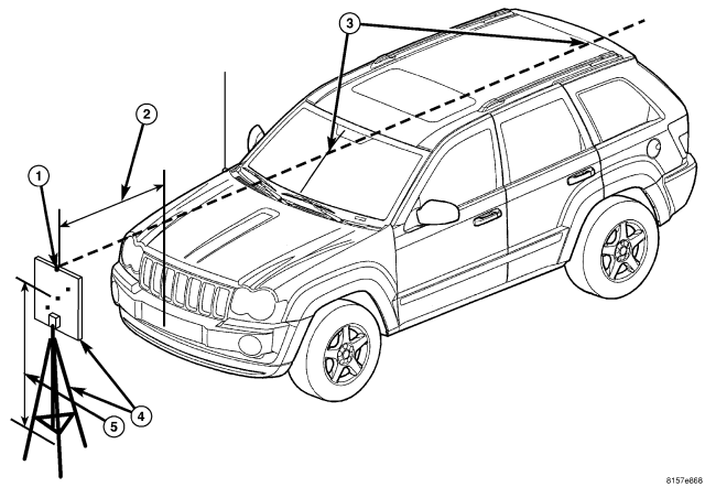
1. Position the vehicle on a level surface in a dimly lit area.
2. Place the aim board and tripod (4) (Special Tool No. 9649) 127 centimeters (50 inches) ahead of the foremost center of the front fascia (2).
3. Sight through the V-notch (1) in the upper edge of the aim board to align and center the board to the imager centerline marks on both the windshield and the liftgate glass (3).
4. Adjust the tripod so that the center Light Emitting Diode (LED) on the aim board is 145 centimeters (57 inches) from the level floor (5).
CALIBRATION PROCEDURE
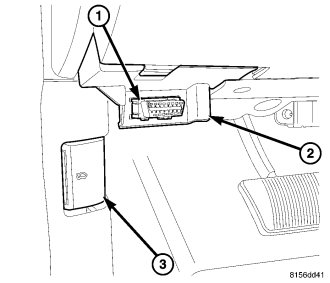
1. Connect a diagnostic scan tool to the Data Link Connector (DLC) (1) below the driver side end of the instrument panel (2).
2. Turn the ignition switch to the ON position.
3. Use the diagnostic scan tool to enter the SmartBeam unit into calibration mode. Look in the diagnostic scan tool under the SmartBeam® or AUTOMATIC HIGH BEAM MODULE/AHBM menu item as appropriate. When the SmartBeam® unit has entered calibration mode, it will be indicated by a continually flashing of the electrochromic LED at a slow rate of once-per-second.
4. Connect the aim board transformer to illuminate the aim board LED units. The electrochromic LED will continue to flash for five to ten seconds, then will stop flashing to indicate that it has completed calibration. If the LED begins to flash at a faster rate (twice-per-second), it indicates that a Diagnostic Trouble Code (DTC) has been recorded. Use the diagnostic scan tool to retrieve the DTC, then refer to the appropriate diagnostic information.