TRANSFER CASE - NV140 - SERVICE INFORMATION
DESCRIPTION
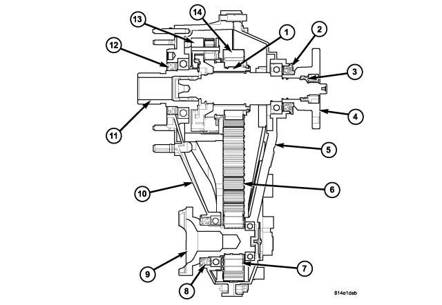
| NV140 Cross Section |
| 1 - MAINSHAFT |
8 - FRONT OUTPUT SEAL |
| 2 - REAR OUTPUT SEAL |
9 - FRONT OUTPUT SHAFT AND FLANGE |
| 3 - SPLINE SEAL |
10 - FRONT CASE |
| 4 - REAR OUTPUT FLANGE |
11 - INPUT GEAR |
| 5 - REAR CASE |
12 - INPUT SEAL |
| 6 - DRIVE CHAIN |
13 - DIFFERENTIAL |
| 7 - FRONT DRIVE SPROCKET |
14 - MAINSHAFT DRIVE SPROCKET |
| 8 - FRONT OUTPUT SHAFT SEAL |
The NV140 is a single-speed transfer case and it is used in the Quadra-Trac I Full-Time 4-Wheel Drive System. It provides full-time 4-wheel drive. The transfer case operates with an open center differential dividing engine torque nearly evenly with 48 percent of engine torque to the front axle and 52 percent of engine torque to the rear axle. The Brake Traction Control System, which combines standard ABS and Traction Control, provides resistance to any wheel that is slipping to allow additional torque transfer to wheels with traction.
The Quadra-Trac I system with NV 140 single-speed transfer case provides the following benefits:
- No shift lever or driver interaction required.
- Full-time four-wheel drive provides smooth operation and vehicle stability under all conditions because torque is constantly being transferred.
- Even torque distribution provides traction to maintain forward motion under most conditions.
- The Brake Traction Control System (BTCS) works in tandem with full-time four-wheel drive. BTCS provides resistance to any wheel that is slipping to allow additional torque transfer to wheels with traction.
- Robust design and improved sealing enhance reliability.
- No maintenance required.
OPERATION
Full-time 4-wheel drive distributes even torque to all wheels under all conditions. The transfer case center differential evenly divides torque to the front and rear axles, while also allowing the driveshafts to rotate at different speeds to account for front and rear wheels traveling different distances while turning. Given that the drive shafts can rotate at different speeds, the vehicle can remain in full-time 4-wheel drive mode indefinitely, even on dry pavement, without threat of damage to the drivetrain. The vehicle uses Brake Traction Control to modulate the torque from one wheel to another across each axle and the transfer case.
REMOVAL
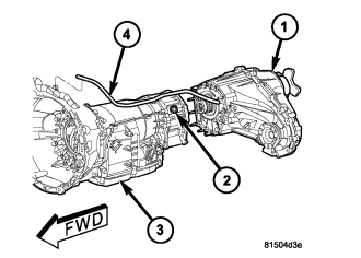
1. Raise vehicle.
CAUTION: Do not allow propshafts to hang at attached end. Damage to joint can result.
2. Remove the front and rear propeller shafts. (Refer to 3 - DIFFERENTIAL & DRIVELINE/PROPELLER SHAFT/PROPELLER SHAFT - REMOVAL)
3. Support transmission with jack stand.
4. Remove rear crossmember and skid plate, if equipped.
5. Disconnect transfer case vent hose (4).
6. Disconnect the wiring connector from the shift motor, if necessary.
7. Support transfer case with transmission jack and secure with chains.
8. Remove nuts (2) attaching transfer case (1) to transmission (3).
9. Pull transfer case and jack rearward to disengage transfer case.
10. Remove transfer case from under vehicle.
DISASSEMBLY
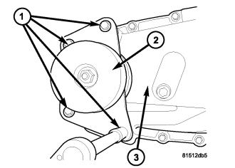
1. Remove the bolts (1) holding the damper (2) to the rear case (3).
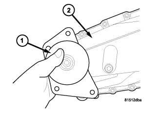
2. Remove the damper (1) from the rear case (2).
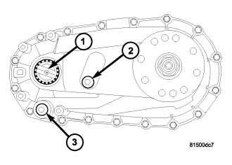
3. Position transfer case on shallow drain pan. Remove drain plug (3) and drain lubricant.
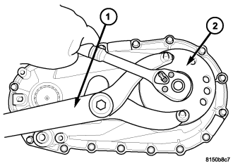
4. Using Holder C-3281 (1), remove the rear output flange (2) nut.
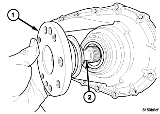
5. Remove the rear output shaft flange (1) from the main shaft (2). If flange is difficult to remove by hand, remove it with bearing splitter, or with standard two jaw puller. Be sure puller tool is positioned securely on flange.
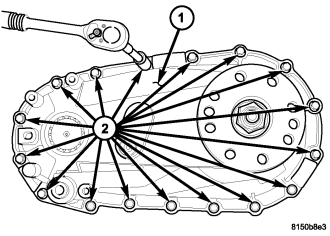
6. Support transfer case so rear case is facing upward and the input gear is not contacting the work surface.
7. Remove bolts (2) holding front case to rear case (1).
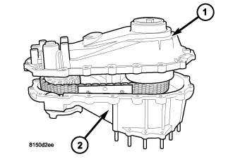
NOTE: Be careful not to damage the front and rear case sealing surfaces.
8. Loosen rear case with a case splitter or suitable tool to break sealer bead. Insert case splitter or suitable tool only into notches provided at each end of case.
9. Remove rear case (1) from front case (2).
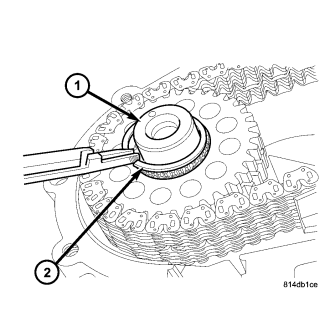
10. Remove mainshaft drive sprocket retaining ring.
11. Remove front output shaft drive sprocket retaining ring (2) from the front output shaft (1).
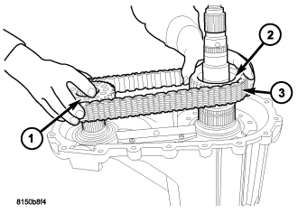
12. Remove the drive sprockets (1, 2) and the drive chains (3) as one.
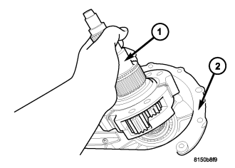
13. Remove the mainshaft and differential assembly (1) from the front case (2).
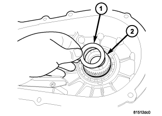
14. Remove the input gear thrust washer (1) from the input gear (2).
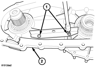
15. Remove the screws (1) holding the chain guide rails to the front case (2).
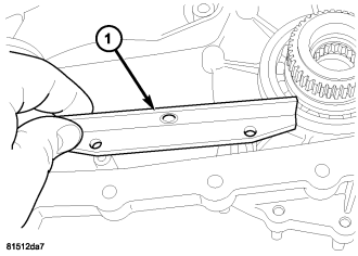
16. Remove the drive chain guide (1) from the transfer case.
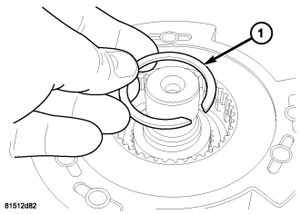
17. Remove the differential snap-ring (1).
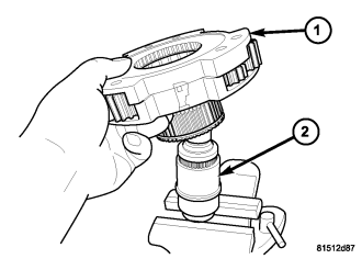
18. Remove the differential assembly (1) from the mainshaft (2).
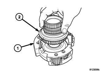
19. Remove the mode hub (2) and mode hub retainer from the differential assembly (1).
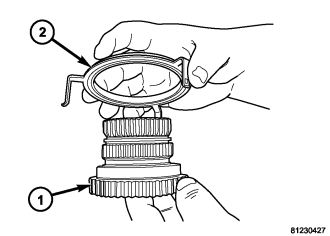
20. Remove the mode hub retainer (2) from the mode hub (1).
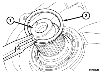
21. Remove the retaining ring (2) from the front output shaft (1).
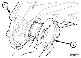
22. Remove the front output shaft assembly (2) from the front case (1) and the front output shaft front bearing.
23. Remove the front output shaft seal with a suitable pry tool or a screw mounted in a slide hammer.
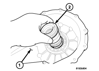
24. Remove the input gear (2) from the front case (1).
25. Remove the input shaft seal with a suitable pry tool or a screw mounted in a slide hammer.
ASSEMBLY
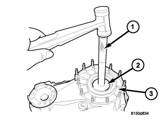
1. Remove the input shaft bearing from the front case (3) with Handle C-4171 (1) and Installer 8693A (2)..
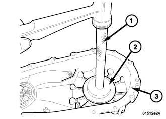
2. Install the new input gear bearing into the front case (3) using Installer 8152 (2), inverted, and Handle C-4171 (1).
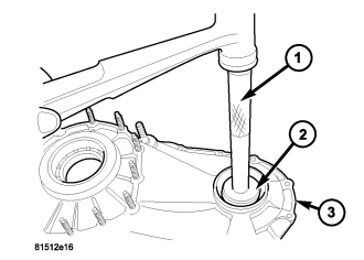
3. Using Installer 7829A (2) and Handle C-4171 (1), remove front output shaft bearing from the front case (3).
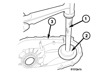
4. Start front output shaft bearing in the front case. Using Installer 8152 (2), inverted, and Handle C-4171 (1), seat the bearing in the front case (3).
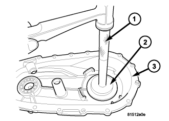
5. Remove the main shaft rear bearing from the rear case using Installer 5066 and Handle C-4171.
6. Install the new main shaft rear bearing into the rear case (3) using Installer 8152 (2), inverted, and Handle C-4171 (1).
7. Install a new front output shaft seal with Installer 6560.
8. Install the front output shaft assembly (2) into the front case (1) and the front output shaft front bearing.
9. Install the retaining ring (2) onto the front output shaft (1).
10. Install the input gear (2) into the front case (1).
11. Install the new input shaft seal with Installer 9672 and Handle C-4171.
12. Lubricate mainshaft splines with recommended transmission fluid.
NOTE: Replace the mode hub retainer if the legs were distorted during removal.
13. Install the mode hub retainer (2) onto the mode hub (1).
14. Install the mode hub (2) and mode hub retainer onto the differential assembly (1). Make sure the retainer is fully seated onto the differential.
15. Install the differential assembly (1) onto the mainshaft (2).
16. Install the differential snap-ring (1).
17. Install the drive chain guide (1) onto the transfer case.
18. Install the screws (1) to hold the chain guide rail to the front case (2). Tighten the screws to 5-8 N·m (44-71 in.lbs.).
19. Install the input gear thrust washer (1) onto the input gear (2).
NOTE: Be sure that the input spline is engaged with the differential assembly.
20. Install the mainshaft and differential assembly (1) into the front case (2) and input gear.
21. Install the drive sprockets (1, 2) and drive chains (3) as one.
22. Install the front output shaft (1) drive sprocket retaining ring (2).
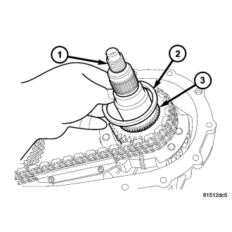
23. Install the mode hub spacer (2) onto the output shaft (1) and the mode hub (3).
24. Install the mainshaft drive sprocket retaining ring onto the mainshaft.
25. Install the transfer case magnet into the magnet pocket.
26. Apply bead of Mopar® Gasket Maker, or equivalent, to mating surface of front case. Keep sealer bead width to maximum of 3 mm (0.125 inch). Do not use excessive amount of sealer as excess will be displaced into case interior.
27. Install the rear case (1) onto the front case (2).
28. Install the bolts (2) to hold the rear case (1) to the front case (3). Tighten the bolts at the alignment dowel locations first. Tighten the bolts to 27 N·m (20 ft.lbs.).
29. Install a new rear output seal into the rear case with Installer C-3972A.
30. Install the rear output flange (1) onto the output shaft (2).
31. Using Holder C-3281 (1), install the rear companion flange (2) nut. Tighten the nut to 122-176 N·m (90-130 ft.lbs.).
32. Install the transfer case damper (1) onto the rear case (2).
33. Install the bolts (1) to hold the damper (2) to the rear case (3). Tighten the bolts to 27 N·m (20 ft.lbs.).
INSTALLATION
1. Mount transfer case on a transmission jack.
2. Secure transfer case to jack with chains.
3. Position transfer case under vehicle.
4. Align transfer case (1) and transmission (3) shafts and install transfer case onto the transmission.
5. Install and tighten transfer case attaching nuts (2) to 35 N·m (26 ft. lbs.) torque.
6. Connect the transfer case vent hose (4).
7. Connect front propeller shaft and install rear propeller shaft. (Refer to 3 - DIFFERENTIAL & DRIVELINE/PROPELLER SHAFT/PROPELLER SHAFT - INSTALLATION)
8. For NV140, fill transfer case with correct fluid. (Refer to LUBRICATION & MAINTENANCE/FLUID TYPES - DESCRIPTION) Correct as necessary.
9. Install the transfer case fill plug (1). Tighten the plug to 20-34 N·m (15-25 ft.lbs.).
10. Install rear crossmember and skid plate, if equipped. Tighten crossmember bolts to 41 N·m (30 ft. lbs.) torque.
11. Remove transmission jack and support stand.
12. Lower vehicle and verify transfer case shift operation.
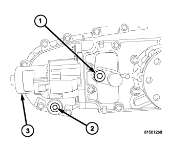
13. For NV146, fill transfer case with correct fluid. (Refer to LUBRICATION & MAINTENANCE/FLUID TYPES - DESCRIPTION) Correct as necessary.
14. Install the transfer case fill plug (1). Tighten the plug to 20-34 N·m (15-25 ft.lbs.).
15. Install rear crossmember and skid plate, if equipped. Tighten crossmember bolts to 41 N·m (30 ft. lbs.) torque.
16. Connect the wiring connector to the shift motor.
17. Remove transmission jack and support stand.
18. Lower vehicle and verify transfer case shift operation.
SPECIAL TOOLS - NV140
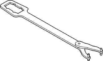
| Holder, Flange - C-3281 |
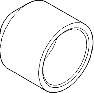
| Installer, Seal - C-3972A |
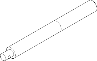
| Handle, Universal - C-4171 |
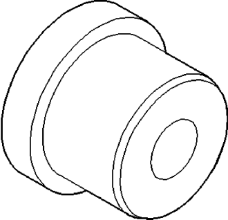
| Installer, Bushing - 5066 |
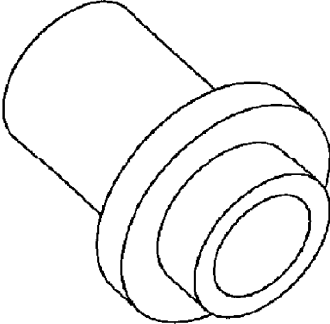
| Installer, Seal - 6560 |
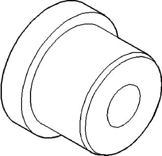
| Installer - 7829A |
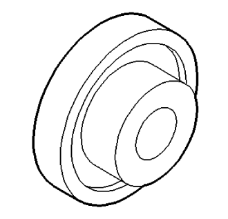
| Installer - 8152 |
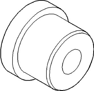
| Installer - 8693A |
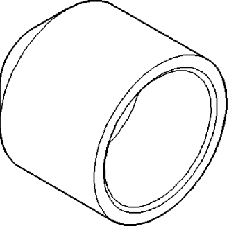
| Installer, Seal - 9672 |