TRANSFER CASE - NV245 - SERVICE INFORMATION
DESCRIPTION
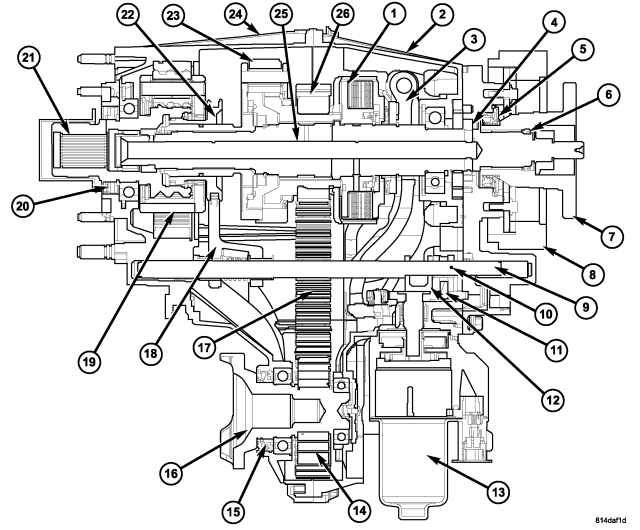
| NV245 Transfer Case |
| 1 - CLUTCH ASSEMBLY |
10 - ROLL PIN |
19 - LOW RANGE PLANETARY |
| 2 - REAR CASE |
11 - SECTOR ROLLER |
20 - INPUT SEAL |
| 3 - CLUTCH LEVER |
12 - ANTI-ROTATION BRACKET |
21
- INPUT GEAR |
| 4 - OIL PUMP |
13 - SHIFT MOTOR AND MODE SENSOR |
22 - RANGE SLEEVE |
| 5 - REAR OUTPUT SEAL |
14 - FRONT OUTPUT SHAFT DRIVE
SPROCKET |
23 - DIFFERENTIAL |
| 6 - SPLINE SEAL |
15 - FRONT OUTPUT SEAL |
24 - FRONT CASE |
| 7 - REAR OUTPUT FLANGE |
16 - FRONT OUTPUT SHAFT AND FLANGE |
25 - MAINSHAFT |
| 8 - DAMPER |
17 - DRIVE CHAIN |
26 - MAINSHAFT DRIVE SPROCKET |
| 9 - SHIFT RAIL |
18 - RANGE FORK |
The NV245 transfer case provides Full-Time Active Four-Wheel Drive for optimum traction in a wide range of conditions and is used in Quadra-Trac® II and Quadra-Drive® II systems. The transfer case center differential distributes torque 48 percent to the front axle and 52 percent to the rear axle along with an electronically controlled clutch pack that is coupled to the center differential for torque biasing. The NV245 electronics provide an active system because it can anticipate and prevent slip. The transfer case can redistribute 100 percent of torque to the front or rear axle, depending on need. For added traction when traversing steep grades, rough terrain or extremely slippery/poor traction surfaces at low speeds, the transfer case can be switched into 4WD Low, which multiplies engine torque 2.72 times and locks the clutch pack for maximum traction at all times. The Neutral mode allows the vehicle to be flat towed behind another vehicle.
Electric shifting is accomplished with a T-handle transfer case lever in the shifter assembly to provide simplified operation and positive engagement of 4 Low. A pushpin button is provided to shifting the transfer case into NEUTRAL.
OPERATION
ACTIVE TRANSFER CASE CONTROLS
Controls for the NV245 transfer case active clutch (torque biasing device) are located in the Final Drive Control Module (FDCM) and communicated on the CAN C bus. The FDCM monitors wheel speeds at the front and rear axles to detect wheel slippage. A complete vehicle dynamics model calculates slip at each tire for given vehicle-operating conditions. The clutch pack in the transfer case is engaged to minimize the speed difference between the front and rear axle, resulting in torque transfer to the axle with higher traction. The electronically controlled wet clutch pack uses an electric motor to actuate a sector plate. The sector plate actuates a clutch lever that applies normal force to the multi-disc wet clutch pack bridging the differential. The clutch discs are alternately splined to the front and rear driveshafts. When normal force is applied to this clutch pack, torque is transferred to equalize speed differences between front and rear axles.
TRANSFER CASE MODES
The transfer case operates in active full-time four-wheel drive (4 High Full-Time) unless the driver chooses 4-wheel drive Low or Neutral. A chrome T-handle momentary contact lever in the shifter assembly labeled 4WD Low allows the driver to select 4WD Low when a set of conditions is met. A separate Neutral pushbutton switch located beside the 4WD Low T-Handle is used by the operator to enter Neutral when a set of conditions is met. An indicator located in the instrument cluster indicates when 4WD Low is active. There is an indicator next to the Neutral button to indicate Neutral position as well as a message in the EVIC in the cluster that states “4WD SYSTEM IN NEUTRAL.”
ELECTRIC SHIFT MECHANISM
All of the switching functions use resistive multiplexing to tell the Final Drive Control Module (FDCM) which mode to select. The FDCM operates an electric motor that shifts the transfer case. The FDCM obtains additional data necessary for operation and to provide diagnostic outputs via the CAN network. The electric shift mechanism helps protect the transfer case against internal damage by preventing a shift to 4WD Low range unless the vehicle speed is below 3 mph (5 km/hr) and the transmission is in Neutral. To shift the transfer case into Neutral for towing the vehicle, the pushpin button next to the range shifter must be depressed with a pen and a set of shift conditions must be met.
Through communication with various modules over the CAN network, the FDCM knows vehicle speed, automatic transmission position, engine run status, ignition status and brake switch position, some or all of which are required to determine whether shifts between 4WD Low, 4WD High or Neutral will be allowed. Diagnostic outputs include fault codes and the ability to “read” switch position and position sensor output. A warning message in the EVIC in the cluster indicates if a malfunction occurs in the electricshift system. A motor and encoder (position sensor) replace a lever on the shaft that shifts the transfer case. When a shift is called for, the motor turns the shaft until the sensor indicates that the correct angular position has been reached. To prevent the transfer case from making unintended shifts, the switch must be in position for 0.25 seconds before a shift will take place. A shift can take up to 1-2 seconds from the time that the switch is moved for full travel. If the shift is not completed in the appropriate time, the module will repeat the action up to five times. Misalignment of the gears in the transfer case may block a shift, in which case the sensor will detect this; the motor will then reverse and try again to complete the shift. Blockage can occur if the vehicle is stationary when the shift is initiated, but if the vehicle is moving as recommended when the shift is initiated, blockage is unlikely. If the shift is not completed after five attempts, the cluster indicator will flash and the driver will have to return the switch to its former position and repeat the operation.
REMOVAL
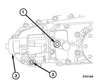
1. Shift transfer case into NEUTRAL.
2. Raise vehicle.
3. Remove transfer case drain plug (2) and drain transfer case lubricant.
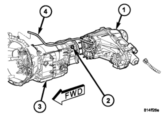
4. Support transmission (3) with jack stand.
5. Remove rear crossmember and skid plate, if equipped.
6. Disconnect front propeller shaft from transfer case at companion flange. Remove rear propeller shaft from vehicle. (Refer to 3 - DIFFERENTIAL & DRIVELINE/PROPELLER SHAFT/PROPELLER SHAFT - REMOVAL)
CAUTION: Do not allow propshafts to hang at attached end. Damage to joint can result.
7. Disconnect the transfer case shift motor and mode sensor connector.
8. Disconnect transfer case vent hose (4).
9. Support transfer case (1) with transmission jack.
10. Secure transfer case to jack with chains.
11. Remove nuts (2) attaching transfer case to transmission.
12. Pull transfer case and jack rearward to disengage transfer case.
13. Remove transfer case from under vehicle.
DISASSEMBLY
1. Place the transfer case in a shallow pan and remove the fill (1) and drain (2) plugs to drain the remainder of the fluid.
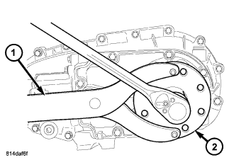
2. Using Holder C-3281 (1), remove the rear flange (2) nut.
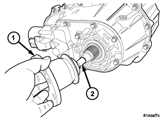
3. Remove the rear output flange (1) from the main shaft (2). If necessary, use a suitable 2 or 3 jaw puller to remove the output flange.
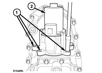
4. Remove the bolts (1) holding the shift motor and mode sensor assembly (2) to the transfer case.
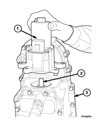
5. Remove the shift motor and mode sensor assembly (1) from the shift sector (2) and the transfer case (3).
6. If necessary, remove the bolts holding the transfer case damper to the transfer case and remove the damper.
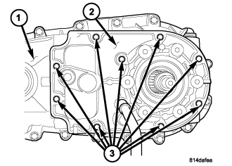
7. Remove the bolts (3) holding the rear cover (2) onto the rear housing (1).
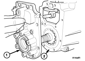
NOTE: Use the pry slots provided and take care not to damage the sealing surface.
8. Remove the rear cover (1) from the rear housing (2).
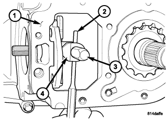
NOTE: Rotate the sector upward to ease the removal of the roll-pin.
9. Using a suitable punch, remove the roll-pin (2) holding the sector roller (4) to the shift rail (3).
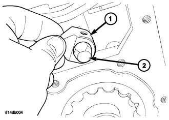
10. Remove the sector roller (1) from the shift rail (2).
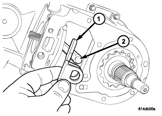
11. Remove the anti-rotation bracket (1) from the shift rail (2).
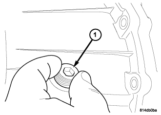
12. Remove the clutch lever rail plug (1) from the rear housing.
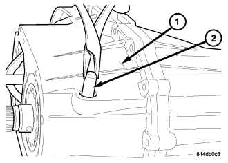
13. Remove the clutch lever rail (2) from the rear housing (1).
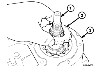
14. Remove the oil pump inner rotor (2) from the main shaft (1) and rear housing (3).
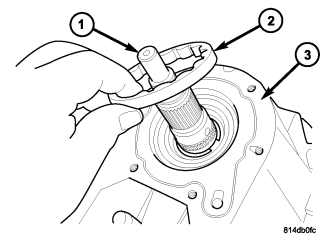
15. Remove the oil pump outer rotor (2) from the main shaft (1) and rear housing (3).
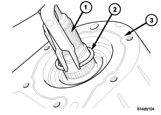
NOTE: Pull upward on the main shaft to ease the removal of the main shaft retaining ring.
16. Remove the rear output shaft (1) retaining ring (2).
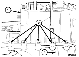
17. Remove the bolts (2) holding the rear housing (1) to the front housing (3).
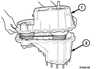
NOTE: Some prying may be necessary to break the seal between the front and rear case. Use care to not damage the sealing surfaces.
18. Remove the rear housing (1) from the front housing (2).
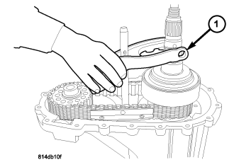
19. Remove the clutch lever assembly (1) from the mainshaft and shift rail.
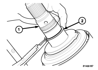
20. Remove the thrust bearing support plate retaining ring (2) from the main shaft (1).
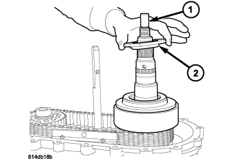
21. Remove the thrust bearing support plate (2) from the main shaft (1).
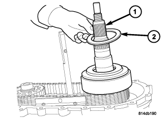
22. Remove the thrust bearing (2) from the main shaft (1).
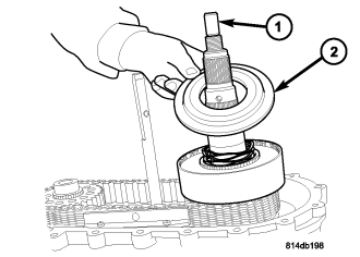
23. Remove the clutch pressure plate (2) from the main shaft (1) and clutch assembly.
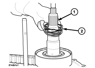
24. Remove the wave spring (2) from the main shaft (1).
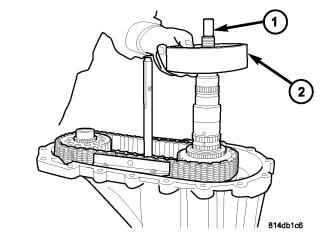
25. Remove the clutch assembly (2) from the main shaft (1).
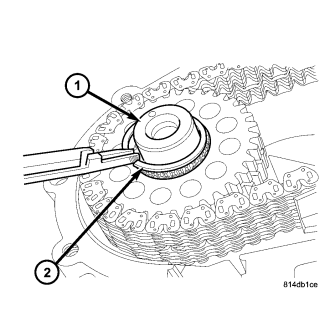
26. Remove the front drive sprocket retaining ring (2) from the front output shaft (1).
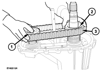
27. Remove the front drive sprocket (1), mainshaft drive sprocket (2), and drive chain (3) as one.
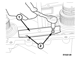
28. Remove the screws (2) holding the chain guide rails (1) to the front housing.
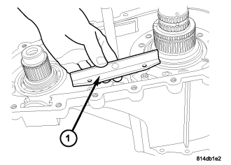
29. Remove the drive chain guides (1) from the transfer case.
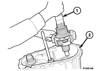
30. Remove the mainshaft and differential assembly (1) from the front housing (2).
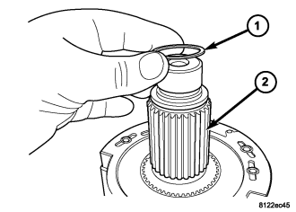
31. Remove intermediate clutch shaft (2) snap-ring (1).
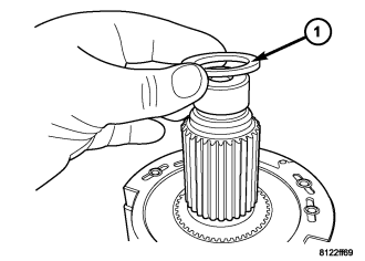
32. Remove the intermediate clutch shaft thrust ring (1).
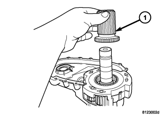
33. Remove the intermediate clutch shaft (1).
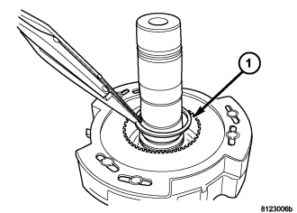
34. Remove the differential snap-ring (1).
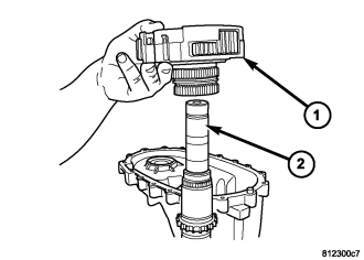
35. Remove the differential assembly (1) from the mainshaft (2).
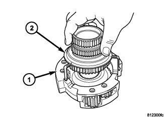
36. Remove the mode hub (2) and mode hub retainer from the differential assembly (1).
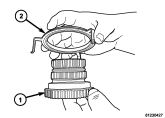
37. Remove the mode hub retainer (1) from the mode hub (2).
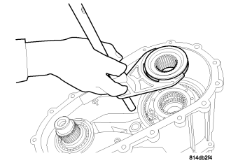
38. Remove the range fork and range hub as one.
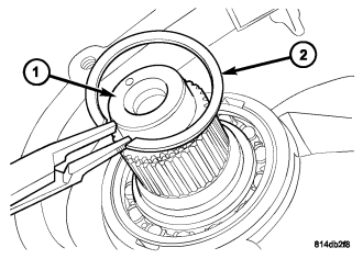
39. Remove the retaining ring (2) from the front output shaft (1).
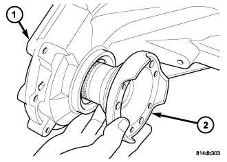
40. Remove the front output shaft (2) from the front housing (1) and the front output shaft front bearing.
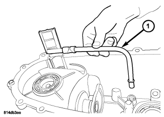
41. Remove the oil pick-up tube and screen (1) from the rear housing.
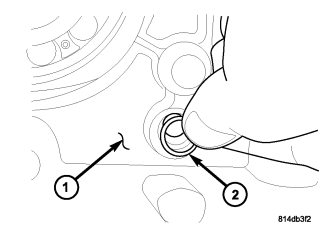
42. Remove the oil pick-up tube o-ring (2) from the rear housing (1).
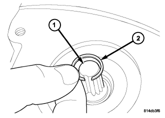
43. Remove the retaining ring (2) from the shift sector shaft (1).
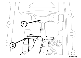
44. Remove the shift sector (2) from the rear housing (1).
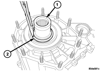
45. Remove the input shaft seal with a suitable pry tool or a screw mounted in a slide hammer.
46. Remove the retaining ring (2) holding the input gear assembly into the front housing.
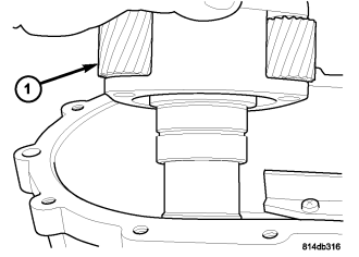
47. Remove the input gear and low range planetary assembly (1) from the front housing.
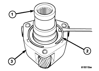
48. Remove the snap-ring (2) holding the input gear (1) into the low range planetary (3).
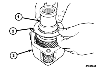
49. Remove the input gear (1) and lock plate (2) from the low range planetary (3) and remove the lock plate.
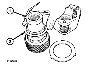
50. Remove the top thrust washer (no tabs) (2) from the input gear (1).
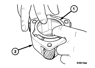
51. Remove the bottom thrust washer (3 tabs) (1) from the low range planetary (2).
ASSEMBLY
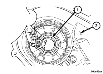
1. While holding the retaining ring tabs apart with suitable snap-ring pliers, remove the input shaft bearing (1) from the front case (2).
2. Transfer the retaining ring to the new housing, if necessary, and install the bearing into the front case.
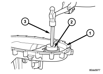
3. Using Installer 6436 and Handle C-4171, remove front output shaft bearing.
4. Start front output shaft bearing in case. Then seat bearing with Handle C-4171 (3) and Installer C-4210 (2).
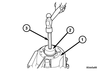
5. Remove the rear main shaft bearing retaining ring from inside the rear housing.
6. Remove the rear output shaft bearing from the rear case using Installer 5066 (2) and Handle C-4171 (3).
7. Install the rear output shaft bearing into the rear case using Remover/Installer 8281 (2) and Handle C-4171 (3).
8. Install the rear output shaft bearing retaining ring into the rear housing, from inside the rear housing.
9. Install the bottom thrust washer (3 tabs) (1) into the low range planetary (2).
10. Install the top thrust washer (no tabs) (2) onto the input gear (1).
11. Install the input gear (1) and lock plate (2) into the low range planetary (3) and install the lock plate.
12. Install the snap-ring (2) to hold the input gear (1) into the low range planetary (3).
13. Install the input gear and low range planetary assembly (1) into the front housing.
14. Install the retaining ring (2) holding the input gear assembly into the front housing.
15. Install the new input shaft seal with Installer 9672 and Handle C-4171.
16. Install the shift sector (2) into the rear housing (1).
17. Install the retaining ring (2) onto the shift sector shaft (1).
18. Install the oil pick-up tube o-ring (2) into the rear housing (1).
19. Prime the oil pickup tube by pouring a little oil into the tube before installation.
20. Install the oil pick-up tube and screen (1) into the rear housing.
21. Install a new front output shaft seal with Installer 6560.
22. Install the front output shaft (2) into the front housing (1) and the front output shaft front bearing.
23. Install the retaining ring (2) onto the front output shaft (1).
NOTE: Check that all three shift pads are present and in good condition on the shift fork.
24. Install the range fork and range hub as one into the input gear/low range planetary.
25. Lubricate mainshaft splines with recommended transmission fluid.
NOTE: Replace the mode hub retainer if the legs were distorted during removal.
26. Install the mode hub retainer (1) onto the mode hub (2).
27. Install the mode hub (2) and mode hub retainer onto the differential assembly (1). Make sure the retainer is fully seated onto the differential.
28. Install the differential assembly (1) onto the mainshaft (2).
29. Install the differential snap-ring (1).
30. Install the intermediate clutch shaft (1).
31. Install the clutch shaft thrust ring (1).
32. Install clutch shaft (2) snap-ring (1).
33. Install the mainshaft and differential assembly (1) into the front housing (2), range sleeve, and input gear/low range planetary.
34. Install the drive chain guides (1) onto the transfer case.
35. Install the screws (2) to hold the chain guide rails (1) to the front housing. Tighten the screws to 5-8 N·m (44-71 in.lbs.).
36. Install the front drive sprocket (1), mainshaft drive sprocket (2), and drive chain (3) as one.
37. Install the front drive sprocket retaining ring (2) onto the front output shaft (1).
38. Install the clutch assembly (2) onto the main shaft (1).
39. Install the wave spring (2) onto the main shaft (1).
CAUTION: When installing the clutch pressure plate, make sure that the wave spring remains piloted on the underside of the plate. Check that the spring does not protrude between the plate and the mainshaft.
40. Install the clutch pressure plate (2) onto the main shaft (1) and clutch assembly.
41. Install the thrust bearing (2) onto the main shaft (1).
42. Install the thrust bearing support plate (2) onto the main shaft (1).
NOTE: The clutch pressure plate must be engaged with the inner drum and held down when installing the retaining ring.
43. Install the thrust bearing support plate retaining ring (2) onto the main shaft (1).
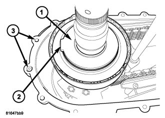
44. Rotate the thrust bearing support plate (1) so that the tab (2) is pointed between the two bolt holes (3) as shown.
45. Install the clutch lever assembly (1) onto the mainshaft and shift rail.
46. Apply bead of Mopar® Gasket Maker, or equivalent, to mating surface of front case. Keep sealer bead width to maximum of 3 mm (0.125 inch). Do not use excessive amount of sealer as excess will be displaced into case interior and potentially clog the oil pump screen.
47. Verify that the tab on the thrust bearing support plate is aligned with the housing alignment dowel furthest from the front output shaft.
48. Install the rear housing (1) into the front housing (2).
49. Install the bolts (2) to hold the rear housing (1) to the front housing (3). Tighten the bolts at the dowel locations first, then the remainder of the bolts in a criss-cross pattern. Tighten the bolts to 27 N·m (20 ft.lbs.).
NOTE: Pull up on the main shaft when installing the retaining ring to ensure that the ring is fully engaged into the groove.
50. Install the rear main shaft (1) retaining ring (2).
Lubricate the oil pump components with transmission fluid before installation.
51. Install the oil pump outer rotor (2) onto the main shaft (1) and into the rear housing (3).
52. Install the oil pump inner rotor (2) onto the main shaft (1) and into the rear housing (3).
53. Install the clutch lever rail (2) into the rear housing (1) and clutch lever.
54. Install the clutch lever rail plug (1) into the rear housing.
55. Install the anti-rotation bracket (1) onto the shift rail (2).
56. Install the sector roller (1) onto the shift rail (2).
57. Using a suitable punch, align the holes in the sector roller with the hole in the shift rail and install the roll-pin to secure the sector roller to the shift rail.
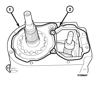
58. Apply bead of Mopar® Gasket Maker, or equivalent, to mating surface of rear housing as shown (2). Keep sealer bead width to maximum of 3 mm (1/8 inch). Do not use excessive amount of sealer as excess could be displaced into the oil pump.
59. Install a new rear output shaft seal into the rear cover with Installer C-3972A.
60. Install the rear cover (1) onto the rear housing (2).
61. Install the bolts (3) holding the rear cover (2) onto the rear housing (1). Tighten the bolts at the dowel locations first, then the remainder of the bolts in a criss-cross pattern. Tighten the bolts to 27 N·m (20 ft.lbs.).
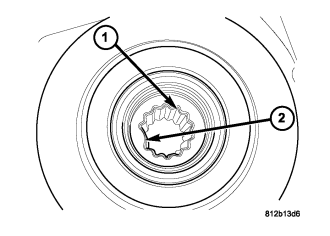
62. Verify that the shift motor o-ring is clean and properly positioned inside the machined o-ring groove of the shift motor.
NOTE: Verify that the missing tooth (2) in the shift motor drive spline (1)...
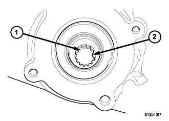
NOTE: ...and the transfer case drive spline (1) missing tooth (2) are aligned. It may be necessary to manually shift the transfer case if the shift motor and transfer case shaft are not aligned.
63. Install the shift motor and mode sensor assembly (1) onto the shift sector (2) and the transfer case (3).
64. Install the bolts (1) to hold the shift motor and mode sensor assembly (2) to the transfer case. Tighten the bolts to 27 N·m (20 ft.lbs.).
65. If necessary, install the transfer case damper onto the transfer case.
66. Install the rear output flange (1) onto the main shaft (2).
67. Using Holder C-3281 (1), install the rear output flange (2) nut. Tighten the bolts to 122-176 N·m (90-130 ft.lbs.).
INSTALLATION
1. Mount transfer case (1) on a transmission jack.
2. Secure transfer case to jack with chains.
3. Position transfer case under vehicle.
4. Align transfer case (2) and transmission (3) shafts and install transfer case onto transmission.
5. Install and tighten transfer case attaching nuts (2) to 35 N·m (26 ft. lbs.) torque.
6. Connect the transfer case vent hose (4) to the transfer case.
7. Install rear crossmember and skid plate, if equipped.
8. Remove transmission jack and support stand.
9. Connect front propeller shaft and install rear propeller shaft. (Refer to 3 - DIFFERENTIAL & DRIVELINE/PROPELLER SHAFT/PROPELLER SHAFT - INSTALLATION)
10. Fill transfer case with correct fluid. Check transmission fluid level. Correct as necessary.
11. Install the transfer case fill plug (1). Tighten the plug to 20-34 N·m (15-25 ft.lbs.).
12. Connect the shift motor and mode sensor wiring connector.
13. Lower vehicle and verify transfer case shift operation.
SPECIAL TOOLS - NV245
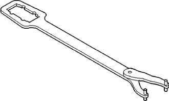
| Holder, Flange - C-3281 |
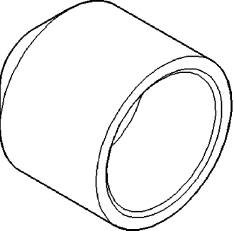
| Installer, Seal - C-3972A |
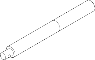
| Handle, Universal - C-4171 |
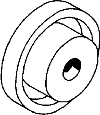
| Installer, Seal - C-4210 |
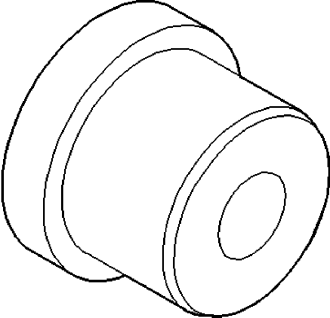
| Installer, Bushing - 5066 |
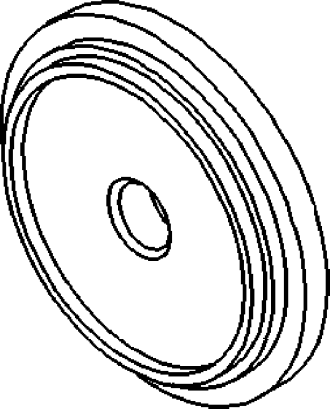
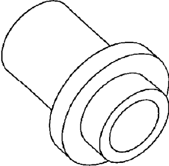
| Installer, Seal - 6560 |
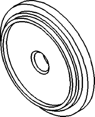
| Installer, Seal - 8281 |
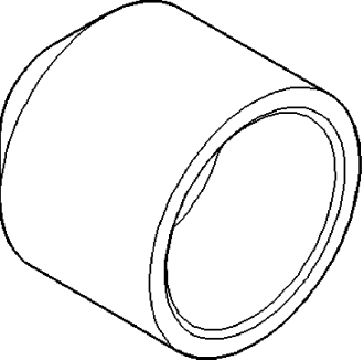
| Installer, Seal - 9672 |