ANTENNA BODY & CABLE
DESCRIPTION
DOMESTIC
The antenna body and cable is secured below the fender panel by the antenna cap nut through a mounting hole in the side of the right front fender. The primary coaxial antenna cable is then routed beneath the fender sheet metal and through a entry hole in the right cowl side panel into the interior of the vehicle. Inside the vehicle, the primary coaxial cable is connected to a secondary instrument panel antenna coaxial cable with an in-line connector that is located behind the right kick panel. The instrument panel antenna cable is then routed behind the instrument panel to the back of the radio.
EXPORT
The primary coaxial antenna cable is routed behind the A-pillar trim, up the right side of the roof panel above the headliner. Inside the vehicle, the primary coaxial cable is connected to a secondary instrument panel antenna coaxial cable with an in-line connector that is located behind the A-pillar trim at one end. At the other end, the cable is connected to the antenna module. The instrument panel antenna cable is then routed behind the instrument panel to the back of the radio.
OPERATION
The antenna body and cable connects the antenna mast (domestic) or quarter glass integral antenna (export) to the radio. The radio antenna is an electromagnetic circuit component used to capture radio frequency signals that are broadcast by local commercial radio stations in both the Amplitude Modulating (AM) and Frequency Modulating (FM) frequency ranges. These electromagnetic radio frequency signals induce small electrical modulations into the antenna as they move past the mast. The antenna body transfers the weak electromagnetic radio waves induced into the antenna into the center conductor of the flexible primary antenna coaxial cable. The braided outer shield of the antenna coaxial cable is grounded through both the antenna body and the radio chassis, effectively shielding the radio waves as they are conducted to the radio. The radio then tunes and amplifies the weak radio signals into stronger electrical signals in order to operate the audio system speakers.
REMOVAL
DOMESTIC
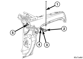
1. Disconnect and isolate the battery negative cable.
2. Remove the antenna mast (1).
3. Remove cover (2).
4. Remove mounting nut (3).
5. Remove bezel adapter.
6. Remove right kick panel trim.
7. Disconnect antenna body and cable from the instrument panel cable. Attach a wire or string (approximately 2 feet in length) to the cable to aid in installation of the new cable.
8. Remove the upper fender mounting bolts. Loosen the two fender mounting bolts located near the upper door hinge (Refer to 23 - BODY/EXTERIOR/FRONT FENDER - REMOVAL).
9. Carefully pull fender out to access the antenna body and cable. Pull cable up through the opening with wire attached.
EXPORT
WARNING: Disable the airbag system before attempting any steering wheel, steering column, seat belt tensioner, side airbag, or instrument panel component diagnosis or service. Disconnect and isolate the battery negative (ground) cable, then wait two minutes for the airbag system capacitor to discharge before performing further diagnosis or service. This is the only sure way to disable the airbag system. Failure to take the proper precautions could result in accidental airbag deployment and possible personal injury.
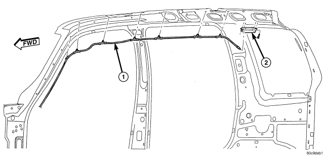
1. Disconnect and isolate the battery negative cable.
2. Remove the assist handles on the right side of the headliner (Refer to 23 - BODY/INTERIOR/ASSIST HANDLE - REMOVAL).
3. Remove the right side visor (Refer to 23 - BODY/INTERIOR/SUN VISOR - REMOVAL).
4. Remove the A-pillar trim (Refer to 23 - BODY/INTERIOR/A-PILLAR TRIM - REMOVAL).
5. Lower headliner as necessary to access antenna cable (1).
6. Disconnect antenna cable from antenna module (2).
7. Remove antenna cable from roof panel by pulling on retaining clips.
8. Disconnect antenna cable from instrument panel antenna cable by disconnecting the antenna connector.
INSTALLATION
DOMESTIC
1. Attached wire to new cable. Pull fender out and insert cable into opening.
2. Pull cable through hole in kick panel area using the attached wire.
3. Connect antenna body cable to the instrument panel cable (5).
4. Install right kick panel trim.
5. Install bezel adapter.
6. Install mounting nut.
7. Install cover.
8. Install antenna mast. Tighten to 50 N·m (37 ft. lbs.). Ensure that the antenna mast is fully seated on antenna base and that there is no gap between the mast and base.
9. Tighten fender mounting bolts near door hinge area.
10. Install and tighten the upper fender mounting bolts (Refer to 23 - BODY/EXTERIOR/FRONT FENDER - INSTALLATION).
11. Connect the battery negative cable.
EXPORT
WARNING: Disable the airbag system before attempting any steering wheel, steering column, seat belt tensioner, side airbag, or instrument panel component diagnosis or service. Disconnect and isolate the battery negative (ground) cable, then wait two minutes for the airbag system capacitor to discharge before performing further diagnosis or service. This is the only sure way to disable the airbag system. Failure to take the proper precautions could result in accidental airbag deployment and possible personal injury.
1. Connect antenna cable (1) to the instrument panel antenna cable.
2. Install antenna cable to the roof panel by pressing retaining clips into position.
3. Connect antenna cable to the antenna module (2).
4. Raise headliner into position.
5. Install A-pillar trim (Refer to 23 - BODY/INTERIOR/A-PILLAR TRIM - INSTALLATION).
6. Install the right side sunvisor (Refer to 23 - BODY/INTERIOR/SUN VISOR - INSTALLATION).
7. Install the assist handles (Refer to 23 - BODY/INTERIOR/ASSIST HANDLE - INSTALLATION).
8. Connect the battery negative cable.