REMOTE SWITCHES
DESCRIPTION
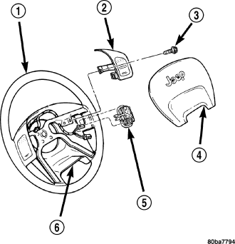
Two rocker-type switches (2) (if equipped) are mounted on the back (instrument panel side) of the steering wheel spokes. The switch on the left spoke is the seek switch and has seek up, seek down, and preset station advance functions. The switch on the right spoke is the volume control switch and has volume up, and volume down functions. The switch on the right spoke also includes a “mode” control that allows the driver to sequentially select AM radio, FM radio, cassette player, CD player or CD changer (if equipped).
OPERATION
The six switches in the two remote radio switch units are normally open, resistor multiplexed momentary switches that are hard wired to the Body Control Module (BCM) through the clockspring. The BCM sends a five volt reference signal to both switch units on one circuit, and senses the status of all of the switches by reading the voltage drop on a second circuit.
When the BCM senses an input (voltage drop) from any one of the remote radio switches, it sends the proper switch status messages on the Programmable Communication Interface (PCI) data bus network to the radio receiver. The electronic circuitry within the radio receiver is programmed to respond to these remote radio switch status messages by adjusting the radio settings as requested. For diagnosis of the BCM or the PCI data bus, the use of a scan tool and the proper Diagnostic Procedures manual are recommended.
DIAGNOSIS AND TESTING - REMOTE SWITCHES
Any diagnosis of the Audio system should begin with the use of scan tool. For information on the use of the scan tool, refer to the appropriate Diagnostic information.
For complete circuit diagrams, refer to the appropriate wiring information.
WARNING: Disable the airbag system before attempting any steering wheel, steering column, seat belt tensioner, side airbag, or instrument panel component diagnosis or service. Disconnect and isolate the battery negative (ground) cable, then wait two minutes for the airbag system capacitor to discharge before performing further diagnosis or service. This is the only sure way to disable the airbag system. Failure to take the proper precautions could result in accidental airbag deployment and possible personal injury.
1. Disconnect and isolate the battery negative cable. Remove the remote radio switch(es) from the steering wheel (Refer to 8 - ELECTRICAL/AUDIO/REMOTE SWITCHES - REMOVAL).
2. Use an ohmmeter to check the switch resistances as shown in the Remote Radio Switch Test chart. If the remote radio switch resistances check OK, go to STEP 3. If not OK, replace the faulty switch.
| Switch | Switch Position | Resistance |
| Right (White) | Volume Up | 1.210 Kilohms ± 1% |
| Right (White) | Volume Down | 3.010 Kilohms ± 1% |
| Right (White) | Mode Advance | 0.0511 Kilohms ± 1% |
| Left (Black) | Seek Up | 0.261 Kilohms ± 1% |
| Left (Black) | Seek Down | 0.681 Kilohms ± 1% |
| Left (Black) | Pre-Set Station Advance | 0.162 Kilohms ± 1% |
3. Reconnect the battery negative cable. Turn the ignition switch to the On position. Check for 5 volts at the radio control mux circuit cavities of the steering wheel wire harness connectors for both remote radio switches. If OK, go to STEP 4. If not OK, repair the open or shorted radio control mux circuit to the Body Control Module (BCM) as required.
4. Disconnect and isolate the battery negative cable. Disconnect the 22-way instrument panel wire harness connector from the BCM. Check for continuity between the remote radio switch ground circuit cavities of the steering wheel wire harness connectors for both remote radio switches and a good ground. There should be no continuity. If OK, go to STEP 5. If not OK, repair the shorted remote radio switch ground circuit to the BCM as required.
5. Check for continuity between the remote radio switch ground circuit cavities of the steering wheel wire harness connectors for both remote radio switches and the 22-way instrument panel wire harness connector for the BCM. There should be continuity. If OK, refer to the proper Diagnostic Procedures manual to test the BCM and the PCI data bus. If not OK, repair the open remote radio switch ground circuit as required.
REMOVAL
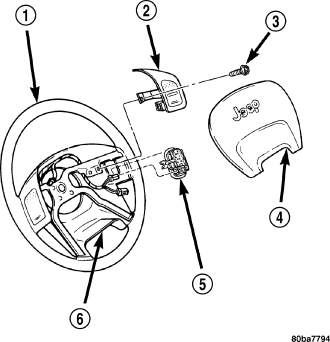
WARNING: Disable the airbag system before attempting any steering wheel, steering column, seat belt tensioner, side airbag, or instrument panel component diagnosis or service. Disconnect and isolate the battery negative (ground) cable, then wait two minutes for the airbag system capacitor to discharge before performing further diagnosis or service. This is the only sure way to disable the airbag system. Failure to take the proper precautions could result in accidental airbag deployment and possible personal injury.
1. Disconnect and isolate the battery negative cable.
2. Remove the driver side airbag from the vehicle (Refer to 8 - ELECTRICAL/RESTRAINTS/DRIVER AIRBAG - REMOVAL).
3. Remove the speed control switches.
4. Unplug the wire harness connector from the remote radio switch (5).
5. Depress the tabs on each side of each switch and push the switch through the rear steering wheel cover.
INSTALLATION
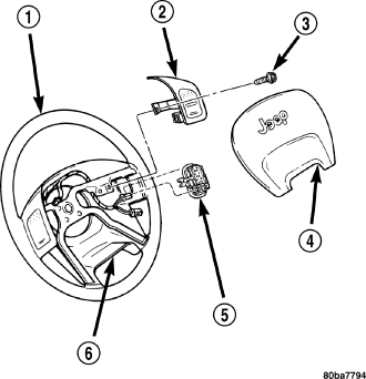
WARNING: Disable the airbag system before attempting any steering wheel, steering column, seat belt tensioner, side airbag, or instrument panel component diagnosis or service. Disconnect and isolate the battery negative (ground) cable, then wait two minutes for the airbag system capacitor to discharge before performing further diagnosis or service. This is the only sure way to disable the airbag system. Failure to take the proper precautions could result in accidental airbag deployment and possible personal injury.
1. Install remote radio switch to the steering wheel.
2. Connect the wire harness to the remote radio switch.
3. Install the speed control switches.
4. Install the driver side airbag (Refer to 8 - ELECTRICAL/RESTRAINTS/DRIVER AIRBAG - INSTALLATION).
5. Connect the battery negative cable.