HCU (HYDRAULIC CONTROL UNIT)
DESCRIPTION
The HCU consists of a valve body, pump motor, and wire harness.
OPERATION
Accumulators in the valve body store extra fluid released to the system for ABS mode operation. The pump provides the fluid volume needed and is operated by a DC type motor. The motor is controlled by the ABM.
The valves modulate brake pressure during antilock braking and are controlled by the ABM.
The HCU provides three channel pressure control to the front and rear brakes. One channel controls the rear wheel brakes in tandem. The two remaining channels control the front wheel brakes individually.
During antilock braking, the solenoid valves are opened and closed as needed. The valves are not static. They are cycled rapidly and continuously to modulate pressure and control wheel slip and deceleration.
During normal braking, the HCU solenoid valves and pump are not activated. The master cylinder and power booster operate the same as a vehicle without an ABS brake system.
During antilock braking, solenoid valve pressure modulation occurs in three stages, pressure increase, pressure hold, and pressure decrease. The valves are all contained in the valve body portion of the HCU.
PRESSURE DECREASE
The outlet valve is opened and the inlet valve is closed during the pressure decrease cycle.
A pressure decrease cycle is initiated when speed sensor signals indicate high wheel slip at one or more wheels. At this point, the ABM closes the inlet then opens the outlet valve, which also opens the return circuit to the accumulators. Fluid pressure is allowed to bleed off (decrease) as needed to prevent wheel lock.
Once the period of high wheel slip has ended, the ABM closes the outlet valve and begins a pressure increase or hold cycle as needed.
PRESSURE HOLD
Both solenoid valves are closed in the pressure hold cycle. Fluid apply pressure in the control channel is maintained at a constant rate. The ABM maintains the hold cycle until sensor inputs indicate a pressure change is necessary.
PRESSURE INCREASE
The inlet valve is open and the outlet valve is closed during the pressure increase cycle. The pressure increase cycle is used to counteract unequal wheel speeds. This cycle controls re-application of fluid apply pressure due to changing road surfaces or wheel speed.
REMOVAL
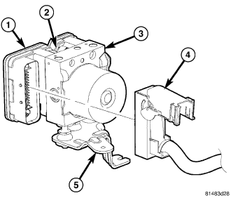
1. Install prop rod on the brake pedal to keep pressure on the brake system.
2. Remove negative battery cable from the battery.
3. Pull up on the ABM harness connector release (4) and remove connector.
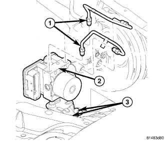
4. Remove brake lines (1) from the ABM (2).
5. Remove ABM (2) mounting nuts (3) and remove ABM(2).
DISASSEMBLY
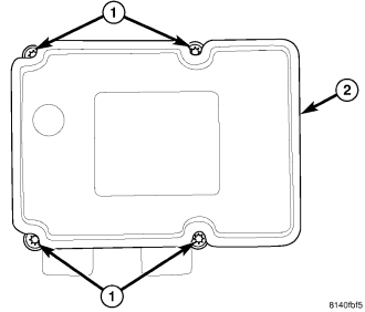
1. Remove the four screws (1) attaching the ABM module to the HCU (2).
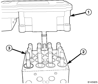
2. Separate the ABM module (1) from the HCU (2) .
ASSEMBLY
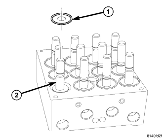
1. Clean any debris off the mating surfaces of the HCU and ABM module.
CAUTION: When installing new O-rings or solenoid valve stem seals, do not use any type of lubricant.
2. If the seals on the components are not new, they must be replaced. Each of the solenoid valve stem seals (1) must be replaced do not reuse solenoid valve stem seals.
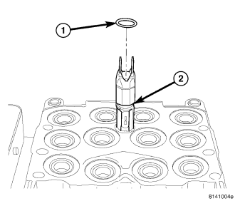
3. The pump/motor connector O-ring (1) should also be replaced if not new
4. Align components and install the ABM module on the HCU .
5. Install the four screws attaching the ABM module to the HCU . Tighten the mounting screws to 2 N·m (17 in. lbs.) torque.
6. If the mounting bracket needs to be installed, install the mounting pins in the HCU as necessary and tighten to 11 N·m (97 in. lbs.) torque. Insert the mounting pins into the grommets mounted in the bracket, then install the single mounting bolt. Tighten the mounting bolt to 11 N·m (97 in. lbs.) torque.
7. Install the HCU in the vehicle (Refer to 5 - BRAKES/HYDRAULIC/MECHANICAL/HCU (HYDRAULIC CONTROL UNIT) - INSTALLATION).
INSTALLATION
NOTE: If the ABM module is being replaced with a new ABM module it must be reprogrammed with the use of a scan tool.
1. Install ABM (2) on the mounting studs (3) .
2. Install mounting nuts. Tighten to 14.1 N·m (125 in. lbs.) .
3. Install brake lines (1) to the ABM (2) and tighten to 20 N·m (180 in. lbs.) .
4. Install wiring harness connector (4) to the ABM (3) and push down on the release to secure the connector.
5. Install negative battery cable to the battery.
6. Bleed ABS brake system (Refer to 5 - BRAKES - STANDARD PROCEDURE).