PUMP - FUEL INJECTION
DESCRIPTION
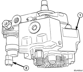
A radial, 3 piston pump with a gear type fuel pump attached to the back, is used as the high pressure pump for fuel pressure generation (Refer to 14 - FUEL SYSTEM - WARNING).
The pump is driven by the timing belt. Pressure is generated independently of the injection process. The pump is lubricated with diesel fuel and is not responsible for fuel injection timing.
OPERATION
Cascade Overflow Valve
Instead of using an electric supply pump, this fuel system uses a gear supply pump located inside the rear of the high pressure pump. The pump is driven by an eccentric on the end of the high pressure pump shaft. The gear pump draws fuel from the fuel tank through the fuel filter.
The pressurized outlet side of the gear pump provides pressurized fuel to a branched circuit internal to the high pressure pump flange, which supples both the fuel quantity solenoid and the cascade overflow valve. Because the gear pump increases fuel flow and pressure as the engine rpm increases, the pressure is regulated by the cascade overflow valve. The cascade overflow valve and gear supply pump are not serviced independently of the high pressure pump.
The cascade overflow valve has two functions:
- Regulation of lubrication fuel to the internal moving parts of the high pressure pump
- Regulation of the fuel pressure being supplied to the fuel quantity solenoid
The cascade valve has a machined center piece that has three drillings. One for overflow, one for lubrication and one for supply. The valve works in three stages based on the pressure entering the inlet of the valve.
Stage 1
When the fuel pressure entering the tip of the cascade valve is between 0 and 3 bar (44 psi), the spring force is not overcome and fuel only flows through the center drilling. This drilling always allows fuel flow through to the pump center ring and lubricates the pump bushings and internal moving parts. This circuit also allows air to bleed during initial cranking and returns the air to the fuel tank. The cascade valve is only in stage one during cranking.
Stage 2
When the fuel entering the cascade valve exceeds 3 bar (44 psi), but is less than 5 bar (73 psi), the center piece of the valve moves against the spring force aligning another passage for lubrication purposes. Stage 2 can be reached during cranking and initial start up.
Stage 3
When fuel pressure exceeds 5 bar (73 psi), the center of the valve aligns with the overflow passage. This stage relieves the pressure into an overflow circuit that sends the fuel back to the inlet side of the gear pump which limits maximum fuel pressure to 5 bar (73 psi). Lubrication fuel also continues to flow though the other ports during this stage. Excess is sent back to the fuel tank through the return circuit.
High Pressure Pumping Plungers
The fuel quantity solenoid supples three high pressure pumping chambers. The pumping chambers have one way inlet valves that allow fuel to flow into the chambers. The valves then close during compression of the fuel and cause the high pressure fuel to overcome a ball and angled seat outlet valve.
All three pumping chambers are tied together in one circuit internal to the pump and provide high pressure fuel up to 1600 bar (23,000 psi) through a steel line, to the fuel rail.
The pump is driven at 1:1 engine speed and is not responsible for injection timing. The pump is only responsible for providing high pressure fuel while the ECM controls the injection timing.
REMOVAL
WARNING: High - pressure lines deliver diesel fuel under extreme pressure from the injection pump to the fuel injectors. This may be as high as 1600 bar (23,200 psi.). Use extreme caution when inspecting for high - pressure fuel leaks. Fuel under this amount of pressure can penetrate skin causing personal injury or death. Inspect for high - pressure fuel leaks with a sheet of cardboard. Wear safety goggles and adequate protective clothing when servicing fuel system.
1. Disconnect negative battery cable.
2. Remove engine cover and bracket (Refer to 9 - ENGINE - REMOVAL) .
3. Evacuate A/C system (Refer to 24 - HEATING & AIR CONDITIONING/PLUMBING - STANDARD PROCEDURE) .
4. Remove cooling fan and fan shroud.
5. Remove accessory drive belt (Refer to 7 - COOLING/ACCESSORY DRIVE/DRIVE BELTS - REMOVAL) .
6. Remove fan support assembly (Refer to 7 - COOLING/ENGINE/RADIATOR FAN - REMOVAL) .
7. Bring piston #1 to TDC, turn crankshaft until notch on the crankshaft hub is at the 12 o'clock position.
8. Looking at the engine from the belt side, rotate the crankshaft 90° clockwise.
9. Remove the intake and exhaust camshaft plugs from the camshaft cover, to introduce the camshaft timing pins VM.1052 Intake, and VM.1053 Exhaust (if the engine is timed correctly, the pins can be installed).
10. Remove timing belt outer cover (Refer to 9 - ENGINE/VALVE TIMING/TIMING BELT / CHAIN COVER(S) - REMOVAL) .
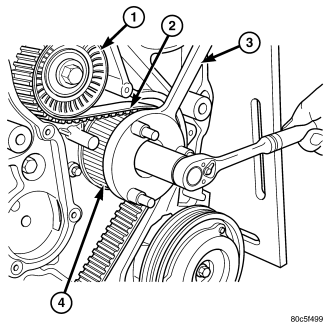
11. Using special tool VM.1055, remove high pressure injection pump sprocket retaining nut .
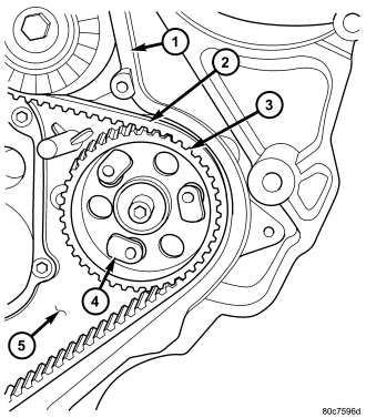
NOTE: The use of special tool VM.1067 will allow you to remove the high pressure injection pump without removing the timing belt from the engine. This will allow you to remove and install the high pressure injection pump without altering engine timing.
12. Install feet from VM.1067 in injection pump sprocket as shown .
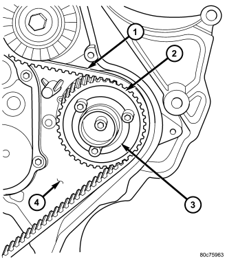
13. Install inner flange of special tool VM.1067 on injection pump sprocket as shown . Secure flange to feet in injection pump sprocket with allen bolts supplied with tool.
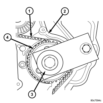
14. Screw the high pressure injection pump sprocket holding plate assembly into flange of VM.1067 Using left hand threaded bolt supplied, secure holding plate assembly to timing belt inner cover.
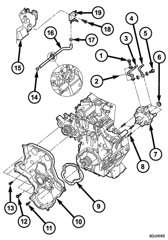
15. Remove the EGR airflow control valve from the intake manifold (Refer to 25 - EMISSIONS CONTROL/EXHAUST GAS RECIRCULATION/VALVE - REMOVAL).
16. Remove high pressure injection pump to fuel rail high pressure line.
17. Disconnect high pressure injection pump quantity control valve electrical connector.
18. Disconnect fuel supply and return lines at high pressure injection pump .
19. Remove alternator to intake manifold bracket.
CAUTION: Care must be taken not to bend the brake vacuum tube when removing high pressure pump.
20. Remove high pressure injection pump retaining nuts and remove pump .
INSTALLATION
WARNING: High - pressure lines deliver diesel fuel under extreme pressure from the injection pump to the fuel injectors. This may be as high as 1600 bar (23,200 psi.). Use extreme caution when inspecting for high - pressure fuel leaks. Fuel under this amount of pressure can penetrate skin causing personal injury or death. Inspect for high - pressure fuel leaks with a sheet of cardboard (refer to 14 - fuel system/fuel delivery - diagnosis and testing). Wear safety goggles and adequate protective clothing when servicing fuel system.
NOTE: If Engine Timing Is Of Concern, (Refer to 9 - ENGINE/VALVE TIMING/TIMING BELT/CHAIN AND SPROCKETS - INSTALLATION) or (Refer to 9 - ENGINE/VALVE TIMING/TMNG BELT/CHAIN TENSIONER&PULLEY - ADJUSTMENTS).
1. Rotate the high pressure pump as necessary to align the key in the pump to the keyway in the sprocket.
2. Loosen bolt in center of injection pump holding plate and slide high pressure injection pump through the accessory bracket into the injection pump sprocket.
3. Install high pressure injection pump retaining nuts . Torque nuts to 27.5N·m (20 ft. lbs.).
4. Unscrew injection pump holding plate (part of VM.1067) from inner timing belt cover and remove .
5. Install high pressure injection pump sprocket retaining nut to hold sprocket in place.
6. Remove flange and feet (both part of VM.1067) from high pressure injection pump sprocket .
7. Using special tool VM.1055 , torque high pressure injection pump sprocket retaining nut to 88.3N·m.(65 ft.lbs.).
8. Remove the camshaft lockpins and install the access plugs.
9. Connect fuel quantity control valve electrical connector.
10. Connect fuel supply and return lines at high pressure injection pump . (Refer to 14 - FUEL SYSTEM - WARNING).
11. Install the EGR airflow control valve (Refer to 25 - EMISSIONS CONTROL/EXHAUST GAS RECIRCULATION/VALVE - INSTALLATION).
12. Install outer timing belt cover (Refer to 9 - ENGINE/VALVE TIMING/TIMING BELT / CHAIN COVER(S) - INSTALLATION) .
13. Install fan support assembly (Refer to 7 - COOLING/ENGINE/RADIATOR FAN - INSTALLATION) .
14. Install accessory drive belt (Refer to 7 - COOLING/ACCESSORY DRIVE/DRIVE BELTS - INSTALLATION).
15. Install cooling fan and shroud assembly.
16. Install charge air cooler outlet hose.
17. Install engine cover and bracket (Refer to 9 - ENGINE - INSTALLATION) .
18. Connect negative battery cable.
19. Evacuate and recharge A/C system (Refer to 24 - HEATING & AIR CONDITIONING/PLUMBING - STANDARD PROCEDURE) .