DIAGNOSIS AND TESTING
- FUEL SYSTEM SUPPLY
- HIGH PRESSURE FUEL LEAKS
- AIR IN FUEL SYSTEM
- FUEL SUPPLY RESTRICTIONS
- FUEL FILTER
- INJECTOR LEAK QUANTITY
FUEL SYSTEM SUPPLY
NOTE: The gear rotor pump in the back of the high pressure pump, draws fuel from the tank, through the filter, to the back of the high pressure pump. The gear rotor pump is capable of drawing up to 20 in. of vacuum, depending on cranking speed. A specification of under 3 in. of vacuum reveals the high pressure pump suspect if there is no air intrusion into the fuel system.
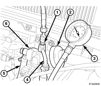
NOTE: There can not be any visible signs of fuel leakage at the filter outlet line or fitting during testing. If a fuel leak is detected, STOP testing, remove special tool fitting #9745, and replace both fuel outlet line washer seals.
Test Set Up
Assumptions for this test are that the fuel gauge is operating properly and that there is know good fuel in the fuel tank.- Disconnect the camshaft position sensor to prevent the vehicle from starting.
- Remove the fuel filter outlet line and install special tool fitting #9745.
- Connect vacuum and pressure gauge # 6828 to the #9745 fitting .
- Re-prime the fuel system to remove all air (Refer to 14 - FUEL SYSTEM/FUEL DELIVERY - STANDARD PROCEDURE).
- Restrict the inlet side of the fuel filter by clamping the inlet hose close to the filter assembly.
- Crank the engine 3–4 times in 10 seconds intervals while monitoring the gauge.
Results
The supply pump should draw at least 3 in. of vacuum. If the supply pump was unable to reach 3 in. of vacuum, replace the high pressure pump (Refer to 14 - FUEL SYSTEM/FUEL DELIVERY/FUEL INJECTION PUMP - REMOVAL).If the pump was able to reach 3 in. of vacuum, continue with this test.
Pressure Test
This test will check the ability of the fuel system to hold pressure.- Reconnect the camshaft position sensor.
- Remove the clamping pliers from the fuel inlet hose.
- Pump the hand primer until 10 psi. is obtained on the pressure side of the gauge.
Results
If the engine starts, refer to the fuel filter restriction test (Refer to 14 - FUEL SYSTEM/FUEL DELIVERY - DIAGNOSIS AND TESTING).If you were able to obtain 10 psi. with the hand primer, refer to the Crank No Start Chart in the Diagnostics manual. If you were unable to obtain 10 psi. with the hand primer, check fuel supply from tank to filter assembly. If the fuel supply is OK, replace the fuel primer/filter assembly (Refer to 14 - FUEL SYSTEM/FUEL DELIVERY/FUEL FILTER / WATER SEPARATOR - REMOVAL).
HIGH PRESSURE FUEL LEAKS
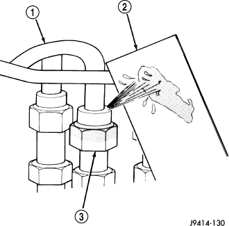
WARNING: High - pressure lines deliver diesel fuel under extreme pressure from the injection pump to the fuel injectors. This may be as high as 1600 bar (23,200 psi.). Use extreme caution when inspecting for high - pressure fuel leaks. Fuel under this amount of pressure can penetrate skin causing personal injury or death. Inspect for high - pressure fuel leaks with a sheet of cardboard. Wear safety goggles and adequate protective clothing when servicing fuel system.
High-pressure fuel leaks can cause starting problems and poor engine performance.
Carefully place a piece of cardboard over the high-pressure fuel lines or suspected area. Move your body and hands away from the area. Start the engine and run till warm. TURN THE ENGINE OFF. Inspect the piece of card board for witness marks. . If a high-pressure line connection is leaking, replace damaged, restricted or leaking high-pressure fuel lines with the correct replacement line.
CAUTION: The high-pressure fuel lines cannot contact each other or other components. Do not attempt to weld high-pressure fuel lines or to repair lines that are damaged. Only use the recommended lines when replacement of high-pressure fuel line is necessary.
AIR IN FUEL SYSTEM
Air will enter the fuel system whenever fuel supply lines, separator filters, injection pump, high-pressure lines or injectors are removed or disconnected. Air trapped in the fuel system can result in hard starting, a rough running engine, engine misfire, low power, excessive smoke and fuel knock.
Inspect the fuel system from the fuel tank to the injectors for loose connections (Refer to 14 - FUEL SYSTEM - WARNING). Leaking fuel is an indicator of loose connections or defective seals. Air can also enter the fuel system between the fuel tank and the fuel filter. Inspect the fuel tank and fuel lines for damage that might allow air into the system.
Trapped air or leaking lines may also be identified by placing a clear piece of fuel line between the fuel supply hose to the filter and the fuel supply hose to the high pressure pump. If a steady stream of large air bubbles are visible in the clear hose while the engine is cranking or running the air intrusion is occurring before the high pressure pump.
With the scan tool connected to the vehicle, select Engine and then select Sensor Display. Page down to view Fuel Pressure Set Point and Actual Fuel Pressure. Start the engine and observe the Fuel Pressure Set Point and the Actual Fuel Pressure. If the Actual Fuel Pressure Oscillates above and below the Fuel Pressure Set Point in a regular cycle, inspect the fuel system for air intrusion.
If the Actual Fuel Pressure gradually drops below the Fuel Pressure Set Point then spikes well above the Fuel Pressure Set Point, replace the fuel rail pressure solenoid (Refer to 14 - FUEL SYSTEM/FUEL INJECTION/FUEL PRESSURE SOLENOID - REMOVAL).
FUEL SUPPLY RESTRICTIONS
LOW-PRESSURE LINES
Fuel supply line restrictions or a restricted fuel filter can cause starting problems and prevent engine from accelerating. The starting problems include; no start, longer cranking times, low power and/or white fog like exhaust.
Inspect all fuel supply lines for restrictions or blockage, including the fuel filter. Flush or replace as necessary.
HIGH-PRESSURE LINES
CAUTION: High pressure lines cannot contact each other or other components. Do not attempt to weld high-pressure fuel lines or to repair lines that are damaged. High pressure lines can be reused only after close inspection for cracks or deformation around the sealing cone. Corroded pipes must be replaced. Use only recommended lines when replacement of high-pressure fuel line is necessary.
Restricted (kinked or bent) high-pressure lines can cause starting problems, poor engine performance, engine mis-fire and white smoke from exhaust (Refer to 14 - FUEL SYSTEM - WARNING).
FUEL FILTER
Refer to the maintenance schedules for the recommended fuel filter replacement intervals (Refer to LUBRICATION & MAINTENANCE/MAINTENANCE SCHEDULES - DESCRIPTION).
The gear supply pump located in the back of the high pressure pump draws fuel from the fuel tank, through the fuel filter and into the high pressure pump. Restricted fuel filters may cause hard starting, no starting, and or white smoke.
Testing The Filter For Restrictions
NOTE: There can not be any visible signs of fuel leakage at the filter outlet line or fitting during testing. If a fuel leak is detected, STOP testing, remove special tool fitting #9745, and replace both fuel line washer seals.
1. Disconnect the fuel filter outlet line at the fuel filter housing.
2. Install fitting, special tool #9745 (1) in place of the fuel line bolt and tighten to 35 N·m (25 ft. lbs.).
3. Connect pressure/vacuum gauge #6828 (3) to the fitting.
4. Prime (2) the fuel filter to remove any entrained air.
5. Start the engine and allow to idle.
6. Monitor and record the vacuum reading on the gauge for 30 seconds.
7. Raise the engine rpm to 1500 rpm and monitor and record the vacuum reading on the gauge for 30 seconds.
8. The vacuum on the gauge should not exceed 10 in. H.g at idle, and throughout the entire rpm range. If the vacuum reading is higher than 10 in. Hg, inspect the low pressure fuel system for restrictions such as, kinked lines or collapsed hoses, before replacing the fuel filter.
9. Remove special tools, install the fuel filter outlet line using the fuel line bolt with two new washer seals. Tighten the fuel line bolt to 35 N·m (25 ft. lbs.).
10. Prime fuel system (Refer to 14 - FUEL SYSTEM - STANDARD PROCEDURE), start the engine, allow to warm, turn engine off and inspect for leaks at the fuel filter and housing.
INJECTOR LEAK QUANTITY
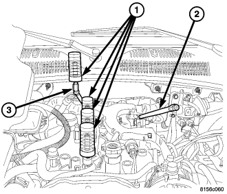
WARNING: Review the high pressure fuel system warning before beginning service (refer to 14 - fuel system - warning).
NOTE: If an injector is found to be out of specification, repeat the test procedure after the injector replacement. Hydraulic flow will take the path of least resistance and multiple failures may be identified.
Perform this test with the engine at operating temperature. This test will assist in determining a defective or internally leaking injector(s) is present by measuring the amount of fuel return.
Cranking Test
1. Turn the ignition off.
2. Remove the engine cover.
NOTE: DO NOT remove the return fuel line clips retaining the return line to the injector. Push IN on the clip to release the hose and then again to install the test vials.
3. Disconnect the return fuel hose at the top of each of the injectors.
NOTE: Care must be taken not to damage the return line check valve between cylinder number four injector and the fuel rail.
4. Block off the disconnected return fuel hose before the fuel return junction on the left rear of the cylinder head cover .
5. Disconnect the camshaft position sensor (CMP).
NOTE: Attach special tool adaptor #9686 to the #4 injector and fill with clean diesel fuel to purge the air from the adaptor, then install the test vial onto the adaptor.
6. Install the test vials onto the injectors and secure with the return hose clips .
7. Crank the engine for ten seconds while monitoring each inner test vial.
8. Evaluate the individual return quantities.
The maximum permissible difference between the return quantity of the individual injectors and the injector with the highest return quantity is 3 graduation marks in the small vial.
| Injector | Graduated Vial Mark | Content |
| 1 | 4 marks, small vial | 4 ml |
| 2 | 1 mark, small vial | 1 ml |
| 3 | 1 mark, small vial | 1 ml |
| 4 | 1/2 mark, small vial | 0.5 ml |
Evaluation
Injector #1 has excessive fuel return quantity, replace the injector. Injectors #2, #3, #4 are OK.9. Perform the cranking test after the repair to assure no other injectors are identified.
Engine Running
1. Start the engine with the test vials in place .
2. Run the engine until the top mark on one of the large graduated vials is obtained.
3. Turn engine off immediately.
4. Evaluate the individual return quantities.
The maximum permissible difference between return quantities of the individual injectors, and the injector with the highest return quantity, is 3 graduation marks.
| Injector | Graduated Vial Mark | Content |
| 1 | 5 marks, large vial | 42 ml |
| 2 | 2 mark, large vial | 21 ml |
| 3 | 2 mark, large vial | 21 ml |
| 4 | Surround, large vial | 8 ml |
Evaluation
Injector #1 has excessive return quantity, replace the injector. Injectors #2, #3, #4 are OK.5. Perform the running test again after the repair to assure no other injectors are identified.
If the injectors pass the quantity test, continue with the diagnostic manual.