MODULE-FUEL PUMP
DESCRIPTION
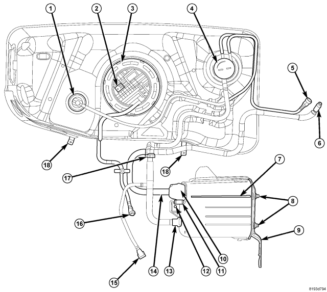
The fuel pump module assembly (2) is located on top of the fuel tank. The complete assembly contains the following components:
- A fuel pressure regulator
- A built-in primary fuel filter
- A separate fuel pick-up, or inlet filter
- An electric fuel pump
- A lockring (3) to retain pump module to tank
- A soft gasket between tank flange and module
- A fuel gauge sending unit (fuel level sensor)
- A fuel line connection
If the electrical fuel pump, primary inlet filter or fuel pressure regulator require service, the fuel pump module must be replaced.
REMOVAL
WARNING: The fuel system may be under a constant pressure (even with the engine off). Before servicing the fuel pump module, the fuel system pressure must be released.
The fuel pump module (2) and pump module lock ring (3) are located on the top of the fuel tank.
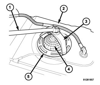
A typical fuel pump module is displayed in the graphic.
1. Drain and remove fuel tank. (Refer to 14 - FUEL SYSTEM/FUEL DELIVERY/FUEL TANK - REMOVAL)
2. Note rotational position of module before attempting removal. An indexing arrow is located on top of module for this purpose.
3. Position Lockring Remover/Installer 9340 (3) into notches on outside edge of lockring (5).
4. Install 1/2 inch drive breaker bar (1) to Lockring Remover/Installer 9340 (3).
5. Rotate breaker bar counterclockwise to remove lockring (5).
6. Remove lockring. The module will spring up slightly when lockring is removed.
7. Remove module from fuel tank. Be careful not to bend float arm while removing.
INSTALLATION
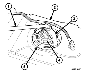
A typical fuel pump module is displayed in the graphic.
1. Using a new seal (gasket), position fuel pump module into opening in fuel tank.
2. Position lockring (5) over top of fuel pump module.
3. Rotate module until embossed alignment arrow points to center alignment mark. This step must be performed to prevent float from contacting side of fuel tank.
4. Install Lockring Remover/Installer 9340 (3) to lockring.
5. Install 1/2 inch drive breaker (1) into Lockring Remover/Installer 9340 (3).
6. Tighten lockring (clockwise) until all seven notches have engaged.
7. Install fuel tank. (Refer to 14 - FUEL SYSTEM/FUEL DELIVERY/FUEL TANK - INSTALLATION)