DAYTIME RUNNING LAMP RELAY
DESCRIPTION
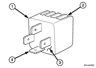
The Daytime Running Lamp (DRL) relay (1) is a solid state relay that is used only on vehicles equipped with the DRL option. The DRL relay is installed in the Junction Block (JB) on the driver side outboard end of the instrument panel. Vehicles equipped with this relay do not have a headlamp high beam relay installed in the JB.
The DRL relay features a die cast aluminum housing that serves to contain the solid state circuitry of the relay as well as to perform as a heat sink (2). Potting material (3) fills the base of the housing to enclose and protect the circuitry.
Four male spade terminals (4) exit the base of the relay housing through the potting material to connect the relay to the vehicle electrical system. These terminals are laid out in a footprint that is similar to that of a conventional International Standards Organization (ISO) relay; however, a standard ISO relay must never be installed in place of the DRL relay.
The DRL relay cannot be adjusted or repaired and, if ineffective or damaged, it must be replaced with a new unit.
OPERATION
The Daytime Running Lamps (DRL) relay is a solid state relay that controls the flow of battery current to the high beam filaments of both headlamp bulbs based upon a duty cycle control input received from the Body Control Module (BCM) of vehicles equipped with the DRL feature. By cycling the DRL relay output, the BCM controls the illumination intensity of the high beam filaments. The DRL relay is connected to the vehicle electrical system through a receptacle in the Junction Block (JB). The inputs and outputs of the DRL relay include:
- Battery Voltage Input - The DRL relay receives battery voltage on a fused B(+) circuit from a fused B(+) fuse in the Power Distribution Center (PDC).
- Ground Input - The DRL relay receives a path to ground through a splice block with an eyelet terminal that is secured by a nut to a ground stud on the driver side instrument panel end bracket near the JB.
- Control Input - The DRL relay control input is received from the BCM or the momentary optical horn (flash-to-pass) output of the multi-function switch through a high beam relay control circuit.
- Control Output - The DRL relay supplies Pulse Width Modulated (PWM) battery voltage to the headlamp high beam filaments through the high beam relay output circuit.
Because of active electronic elements within the DRL relay, it cannot be diagnosed using conventional diagnostic tools and procedures. If the DRL relay is believed to be ineffective, test and repair the headlamp system as necessary. If no problem is found in the headlamp system, replace the DRL relay with a known good unit to confirm system operation.
REMOVAL
WARNING: To avoid personal injury or death, on vehicles equipped with airbags, disable the supplemental restraint system before attempting any steering wheel, steering column, airbag, occupant classification system, seat belt tensioner, impact sensor, or instrument panel component diagnosis or service. Disconnect and isolate the battery negative (ground) cable, then wait two minutes for the system capacitor to discharge before performing further diagnosis or service. This is the only sure way to disable the supplemental restraint system. Failure to take the proper precautions could result in accidental airbag deployment.
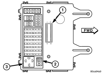
NOTE: The DRL relay is installed in the Junction Block (JB) on the driver side outboard end of the instrument panel. Vehicles equipped with this relay MUST NOT have a headlamp high beam relay installed in the JB. Also, although the terminals of the DRL relay are laid out in a footprint that is similar to that of a conventional International Standards Organization (ISO) relay, a standard ISO relay MUST NEVER be installed in the place of the DRL relay.
1. Disconnect and isolate the battery negative cable.
2. Remove the trim from the driver side end of the instrument panel. (Refer to 23 - BODY/INSTRUMENT PANEL/INSTRUMENT PANEL END CAP - REMOVAL).
3. Remove the Daytime Running Lamp (DRL) relay (3) by grasping it firmly and pulling it straight out from the receptacle in the JB.
INSTALLATION
WARNING: To avoid personal injury or death, on vehicles equipped with airbags, disable the supplemental restraint system before attempting any steering wheel, steering column, airbag, occupant classification system, seat belt tensioner, impact sensor, or instrument panel component diagnosis or service. Disconnect and isolate the battery negative (ground) cable, then wait two minutes for the system capacitor to discharge before performing further diagnosis or service. This is the only sure way to disable the supplemental restraint system. Failure to take the proper precautions could result in accidental airbag deployment.
NOTE: The DRL relay is installed in the Junction Block (JB) on the driver side outboard end of the instrument panel. Vehicles equipped with this relay MUST NOT have a headlamp high beam relay installed in the JB. Also, although the terminals of the DRL relay are laid out in a footprint that is similar to that of a conventional International Standards Organization (ISO) relay, a standard ISO relay MUST NEVER be installed in the place of the DRL relay.
1. Position the Daytime Running Lamp (DRL) relay to the proper receptacle (3) in the JB. The adjacent receptacle (2) must NOT be populated by a headlamp high beam relay on a vehicle that is equipped with a DRL relay.
2. Align the DRL relay terminals with the cavities in the JB receptacle.
3. Push firmly and evenly on the top of the DRL relay until the relay base is fully seated in the JB receptacle.
4. Reinstall the trim onto the driver side outboard end of the instrument panel. (Refer to 23 - BODY/INSTRUMENT PANEL/INSTRUMENT PANEL END CAP - INSTALLATION).
5. Reconnect the battery negative cable.