HAZARD SWITCH
DESCRIPTION
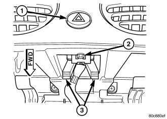
The hazard switch is integral to the hazard switch module, which is secured near the center of instrument panel just above the radio. Only the hazard switch button (1) is visible through a dedicated, beveled, circular opening in the instrument panel between the two center panel outlets of the heat and air conditioning system. A red, stencil-like International Control and Display Symbol icon for Hazard Warning identifies the hazard switch button. The remainder of the hazard switch module is concealed behind the instrument panel.
All of the circuitry and components of the hazard switch module are contained within a molded black plastic housing. On the opposite end of the housing from the switch button is an integral connector receptacle and a stamped steel mounting bracket. The mounting bracket includes two latch feature tabs (3) that extend downward to support the back of the housing. These tabs engage the edge of the mounting hole provided for the switch in the instrument panel above the radio opening. The switch module housing also has an integral short, dowel-like alignment pin on each side just behind the switch button that is engaged in integral ramp formations in the instrument panel two align and support the face of the module. Finally, a single screw (2) through the top of the radio opening securely fastens the switch module to the instrument panel.
The switch module is connected to the vehicle electrical system through a single dedicated take out and connector of the instrument panel wire harness. Within the hazard switch module is the hazard switch circuitry, which includes a circuit board with both the hazard switch and the electronic combination flasher circuitry. The circuitry of the combination flasher performs both the hazard flasher and the turn signal flasher functions.
The hazard switch module cannot be adjusted or repaired and, if ineffective or damaged, it must be replaced as a unit.
OPERATION
The hazard switch button is slightly recessed in the instrument panel when the switch is in the OFF position, and latches at a position that is flush with the outer surface of the instrument panel when in the ON position. The hazard switch module circuit board includes miniature relays that produce audible clicking to emulate the sound of a conventional flasher whenever the turn signals or the hazard warning system are activated.
The hazard switch module receives battery voltage on a fused B(+) circuit from a fuse in the Junction Block (JB) at all times for operation of the hazard warning, and on a fused ignition switch output (run) circuit from another fuse in the JB whenever the ignition switch is in the ON position for operation of the turn signals. The module receives a path to ground through a splice block secured by a nut to a ground stud on the driver side instrument panel end bracket near the JB.
Inputs to and outputs from the hazard switch module include:
- Panel Lamps Dimmer Input - A non-serviceable incandescent bulb soldered onto the hazard switch module provides illumination of the switch button when the exterior lighting is turned ON through the fused panel lamps dimmer switch signal circuit. This bulb flashes ON and OFF at full intensity whenever the hazard switch button is activated, regardless of the status of the exterior lighting.
- Hazard Switch Input - The combination flasher receives an internal ground input from the hazard switch to request hazard flasher operation.
- Multi-Function Switch Input - The combination flasher receives separate ground inputs from the multi-function switch on right and left turn switch sense circuits to request turn signal flasher operation.
- Body Control Module Input - The Body Control Module (BCM) can request hazard flasher operation by providing a ground path to the combination flasher through a hazard lamp control circuit.
- Turn Signal Output - The combination flasher responds to the flasher inputs by energizing and de-energizing two miniature relays on the module circuit board. These relays control the switch output through the right and left turn signal circuits. One relay controls the right lamps, while the other controls the left.
Because of active electronic elements within the hazard switch module, it cannot be tested using conventional diagnostic tools or procedures. If a problem is noted with turn signal or hazard warning system operation, test and confirm the turn signal and hazard warning lighting circuits are in good condition before replacing the hazard switch module with a known good unit to confirm system operation.
REMOVAL
WARNING: To avoid personal injury or death, on vehicles equipped with airbags, disable the supplemental restraint system before attempting any steering wheel, steering column, airbag, occupant classification system, seat belt tensioner, impact sensor, or instrument panel component diagnosis or service. Disconnect and isolate the battery negative (ground) cable, then wait two minutes for the system capacitor to discharge before performing further diagnosis or service. This is the only sure way to disable the supplemental restraint system. Failure to take the proper precautions could result in accidental airbag deployment.
1. Disconnect and isolate the battery negative cable.
2. Remove the radio from the instrument panel. (Refer to 8 - ELECTRICAL/AUDIO/RADIO - REMOVAL).
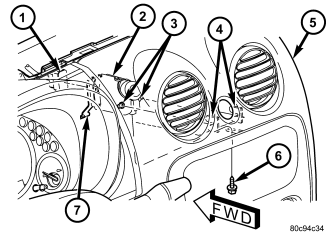
3. Remove the screw (6) at the top of the instrument panel radio opening that secures the hazard switch (2) to the instrument panel (5).
4. Reach through the radio opening to access the two latch tabs (7) of the stamped metal hazard switch mounting bracket.
5. Pull rearward and downward on the latch tabs of the switch mounting bracket far enough to disengage them from the instrument panel trim.
6. Push the hazard switch button through the button opening far enough to disengage the alignment pins (3) on each side of the switch housing from the saddle-like ramp formations (4) on the back of the instrument panel trim.
7. Pull the switch down into the radio opening far enough to access and disconnect the instrument panel wire harness connector (1) from the back of the switch.
8. Remove the hazard switch through the instrument panel radio opening.
INSTALLATION
WARNING: To avoid personal injury or death, on vehicles equipped with airbags, disable the supplemental restraint system before attempting any steering wheel, steering column, airbag, occupant classification system, seat belt tensioner, impact sensor, or instrument panel component diagnosis or service. Disconnect and isolate the battery negative (ground) cable, then wait two minutes for the system capacitor to discharge before performing further diagnosis or service. This is the only sure way to disable the supplemental restraint system. Failure to take the proper precautions could result in accidental airbag deployment.
1. Position the hazard switch module (2) into the instrument panel (5) radio opening.
2. Reconnect the instrument panel wire harness connector (1) to the back of the switch housing.
3. Reach through the instrument panel radio opening to position the hazard switch for installation.
4. Guide the hazard switch button through the button opening of the instrument panel, which will engage the alignment pins (3) on each side of the switch housing into the saddle-like ramp formations (4) on the back of the instrument panel trim.
5. Press upward on the back of the hazard switch until the latch tabs (7) of the mounting bracket are both engaged with the instrument panel trim.
6. Install and tighten the screw (6) that secures the switch to the top of the instrument panel radio opening. Tighten the screw to 2 N·m (17 in. lbs.).
7. Reinstall the radio into the instrument panel. (Refer to 8 - ELECTRICAL/AUDIO/RADIO - INSTALLATION).
8. Reconnect the battery negative cable.