REMOTE KEYLESS ENTRY MODULE
DESCRIPTION
When an RKE lock message is sent to the Body Control Module (BCM), the BCM actuates the doors and the tailgate lock, the interior lighting is turned off, the horn chirps (if this feature is enabled), the exterior lamps flash (if this feature is enabled) and, if the vehicle is so equipped, the Vehicle Theft Security System (VTSS) is armed. When an RKE unlock message is sent to the BCM, the BCM actuates the driver side front door (or all doors and the tailgate if this feature is enabled) unlock, the interior lighting is turned on and, if the vehicle is so equipped, the VTSS is disarmed. The exterior lamps flash if this feature is enabled
When an RKE panic message is sent to the BCM, the BCM actuates the driver side front door (or all doors and the tailgate if this feature is enabled) unlock, the interior lighting is turned on and, if the vehicle is so equipped, the VTSS is disarmed. The panic message will also cause the exterior lamps (including the headlights) to flash, and the horn to pulse for about three minutes, or until a second panic message is sent to the BCM. A vehicle speed of about 25.7 Km/h (15 mph) will also cancel the panic event.
OPERATION
Whenever the vehicle battery power is interrupted, the Remote Keyless Module (RKE) Module will retain all vehicle access codes in its memory. When replacing or adding a key fob transmitter (maximum of 4) a scan tool is required to program the RKE Module to accept the new Vehicle Access Code if a customer owned transmitter is not available.
If a functioning transmitter is available, (Refer to 8 - ELECTRICAL/POWER LOCKS/KEYLESS ENTRY TRANSMITTER - STANDARD PROCEDURE)
DIAGNOSIS AND TESTING - REMOTE KEYLESS ENTRY MODULE
Refer to the proper Body Diagnostic Procedures Manual for testing the Remote Keyless Entry system using a scan tool.
REMOVAL
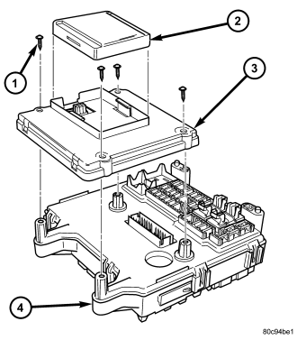
1. Disconnect and isolate the battery negative cable.
2. Remove the Junction Block (JB) (4) (Refer to 8 - ELECTRICAL/POWER DISTRIBUTION/JUNCTION BLOCK - REMOVAL).
3. Remove Remote Keyless Entry module (2) from Body Control Module (3).
INSTALLATION
1. Install Remote Keyless Entry module (2) to Body Control Module (3).
2. Install Junction Block (JB) (4) (Refer to 8 - ELECTRICAL/POWER DISTRIBUTION/JUNCTION BLOCK - INSTALLATION).
3. Connect the battery negative cable.