DIAGNOSIS AND TESTING
POWER SEAT SWITCH
For complete circuit diagrams, refer to the appropriate wiring information. The wiring information includes wiring diagrams, proper wire and connector repair procedures, details of wire harness routing and retention, connector pin-out information and location views for the various wire harness connectors, splices and grounds.
1. Disconnect and isolate the battery negative cable.
2. Remove the power seat switch, (Refer to 8 - ELECTRICAL/POWER SEATS/DRIVER SEAT SWITCH - REMOVAL).
3. Use an ohmmeter to test the continuity of the power seat switch in each switch position, refer to the switch illustration and the Power Seat Switch Direction Chart. See the Power Seat Switch Continuity Chart for test results. If OK, (Refer to 8 - ELECTRICAL/POWER SEATS/POWER SEAT TRACK - DIAGNOSIS AND TESTING) for further power seat system diagnosis. If not OK, replace the faulty power seat switch assembly.
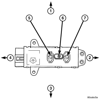
NOTE: The left power seat switch is shown, the right power seat switch is similar.
| ILLUSTRATION CALL-OUT NUMBER | POWER SEAT SWITCH DIRECTION |
| 1 | UP |
| 2 | REARWARD |
| 3 | DOWN |
| 4 | FORWARD |
| 5 | FRONT RISER SWITCH |
| 6 | CENTER SEAT SWITCH |
| 7 | REAR RISER SWITCH |
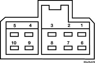
| SWITCH POSITION | CONTINUITY BETWEEN PINS | |
| LEFT POWER SEAT | RIGHT POWER SEAT | |
| OFF | PIN 1 to 3 | PIN 1 to 3 |
| PIN 1 to 6 | PIN 1 to 6 | |
| PIN 1 to 7 | PIN 1 to 7 | |
| PIN 1 to 8 | PIN 1 to 8 | |
| PIN 1 to 9 | PIN 1 to 9 | |
| PIN 1 to 10 | PIN 1 to 10 | |
| FRONT RISER UP | PIN 1 to 8 | PIN 1 to 8 |
| PIN 5 to 9 | PIN 5 to 8 | |
| FRONT RISER DOWN | PIN 1 to 9 | PIN 1 to 9 |
| PIN 5 to 8 | PIN 5 to 9 | |
| CENTER SWITCH FORWARD | PIN 1 to 6 | PIN 1 to 6 |
| PIN 5 to 3 | PIN 5 to 3 | |
| CENTER SWITCH REARWARD | PIN 1 to 3 | PIN 1 to 3 |
| PIN 5 to 6 | PIN 5 to 6 | |
| REAR RISER UP | PIN 1 to 7 | PIN 1 to 7 |
| PIN 5 to 10 | PIN 5 to 7 | |
| REAR RISER DOWN | PIN 1 to 10 | PIN 1 to 10 |
| PIN 5 to 7 | PIN 5 to 10 | |