WINDOW SWITCH
DIAGNOSIS AND TESTING - WINDOW SWITCH
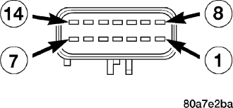
1. Remove the switch to be tested (Refer to 8 - ELECTRICAL/POWER WINDOWS/POWER WINDOW SWITCH - REMOVAL).
2. Using an ohmmeter, Test front switch for continuity.
| SWITCH POSITION | CONTINUITY BETWEEN |
| OFF | 14 AND 4 |
| 14 AND 5 | |
| 14 AND 6 | |
| 14 AND 7 | |
| 14 AND 9 | |
| 14 AND 11 | |
| 14 AND 12 | |
| 14 AND 13 | |
| LEFT FRONT UP | 10 AND 11 |
| LEFT FRONT DOWN | 10 AND 9 |
| RIGHT FRONT UP | 10 AND 12 |
| RIGHT FRONT DOWN | 10 AND 13 |
| LEFT REAR UP | 10 AND 5 |
| LEFT REAR DOWN | 10 AND 4 |
| RIGHT REAR UP | 10 AND 7 |
| RIGHT
REAR DOWN | 10 AND 6 |
| LOCKOUT (LOCKED) | NO CONTINUITY BETWEEN 10 AND 2 |
| LOCKOUT (UNLOCKED) | 10 AND 2 |
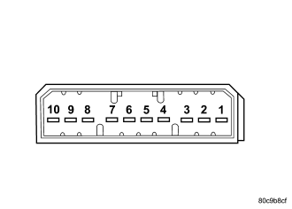
3. If the proper results are not obtained, replace the front window switch.
4. Test rear switch for continuity.
| SWITCH POSITION | CONTINUITY BETWEEN |
| OFF | 1 AND 3 |
| 4 AND 2 | |
| 7 AND 10 | |
| 8 AND 9 | |
| LEFT UP | 10 AND 6 |
| LEFT DOWN | 6 AND 8 |
| RIGHT UP | 5 AND 2 |
| RIGHT DOWN | 5 AND 3 |
5. If the proper results are not obtained, replace the rear window switch.
The power window master switch has a Auto-Down feature on both front windows. The switch is equipped with two detent positions when actuating the power window OPEN. The first detent position allows the window to roll down and stop when the switch is released. The second detent position actuates an integral express roll down relay that rolls the window down after the switch is released. When the express down circuit senses stall current (window has reached end of down travel), the switch will turn current off to the motor. The AUTO feature can be cancelled by actuating the switch UP or DOWN while window is in motion. If the electronic circuit in the switch fails to detect a stall current, the auto down circuit will time out within 9 to 14 seconds.
REMOVAL
FRONT
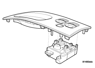
1. Disconnect and isolate the battery negative cable.
2. Remove the shift bezel.
3. Remove the mounting fasteners and switch.
4. Disconnect electrical harness connector.
REAR
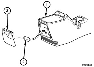
1. Disconnect and isolate the battery negative cable.
2. Using a trim stick, gently pry the switch (3) from the console (1).
3. Disconnect electrical harness connector (2).
INSTALLATION
FRONT
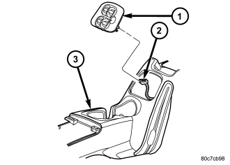
1. Connect electrical harness connector (2) to switch (1).
2. Install switch to shifter bezel. Install and tighten mounting fasteners.
3. Install shifter bezel.
4. Connect battery negative cable.
REAR
1. Connect electrical harness connector (2) to switch (3).
2. Install switch into opening in console (1) and press into place.
3. Connect battery negative cable.