DIAGNOSIS AND TESTING
REAR WINDOW DEFOGGER SWITCH
The rear window defogger switch and timer circuit may be tested in the vehicle with or without the DRB III® scan tool.
TESTING WITH SCAN TOOL
Using a DRB III® scan tool, refer to the proper Body Diagnostic Procedures Manual.
TESTING WITHOUT SCAN TOOL
NOTE: For circuit descriptions and diagrams of the rear window defogger (EBL) system, refer to 8W - WIRING DIAGRAM INFORMATION.
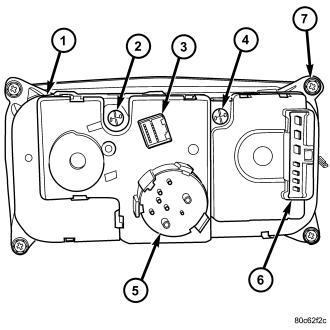
1. Remove the A/C-heater control from the instrument panel (refer to 24 - HEATING & AIR CONDITIONING/CONTROLS/CONTROL-A/C HEATER - REMOVAL).
2. Using a ohmmeter, check for continuity between the ground circuit cavity of the defogger switch wire harness connector and a good ground. There should be continuity. If OK, go to STEP 3. If not OK, repair the open circuit as required.
3. Check for continuity between the ground circuit terminal and the rear window defogger relay output terminal (3) on the back of the A/C-heater control. There should be momentary continuity as the defogger switch is pressed, and then no continuity. If OK, (refer to 8 - ELECTRICAL/HEATED GLASS - DIAGNOSIS AND TESTING). If not OK, replace the inoperative A/C-heater control.