TRANSFER CASE - NV242
- DESCRIPTION
- OPERATION
- DIAGNOSIS AND TESTING - TRANSFER CASE - NV242
- REMOVAL
- DISASSEMBLY
- CLEANING
- INSPECTION
- ASSEMBLY
- INSTALLATION
DESCRIPTION
The NV242 is a full-time transfer case. It provides full time 2-wheel, or 4-wheel drive operation.
A differential in the transfer case is used to control torque transfer to the front and rear axles. A low range gear provides increased low speed torque capability for off road operation. The low range provides a 2.72:1 reduction ratio.
The geartrain is mounted in two aluminum case halves attached with bolts. The mainshaft front and rear bearings are mounted in aluminum retainer housings bolted to the case halves.
TRANSFER CASE IDENTIFICATION
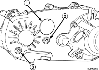
A circular ID tag (1) is attached to the rear case of each transfer case. The ID tag provides the transfer case model number, assembly number, serial number, and low range ratio.
The transfer case serial number also represents the date of build.
OPERATING RANGES
NV242 operating ranges are 2WD (2-wheel drive), 4x4 part-time, 4x4 full time, 4 Lo, and Neutral.
The 2WD and 4x4 full time ranges can be used at any time and on any road surface.
The 4x4 part-time and 4 Lo ranges are for off road use only. The only time these ranges can be used on hard surface roads, is when the surface is covered with snow and ice.
SHIFT MECHANISM
Operating ranges are selected with a floor mounted shift lever. The shift lever is connected to the transfer case range lever by a shift cable. A straight line shift pattern is used. Range positions are marked on the shifter bezel cover plate, or on the shift knob.
OPERATION
The input gear is splined to the transmission output shaft. It drives the mainshaft through the planetary gear and range hub. The front output shaft is operated by a drive chain that connects the shaft to a drive sprocket on the mainshaft. The drive sprocket is engaged/disengaged by the mode fork, which operates the mode sleeve and hub. The sleeve and hub are not equipped with a synchro mechanism for shifting.
DIAGNOSIS AND TESTING - TRANSFER CASE - NV242
| CONDITION |
POSSIBLE CAUSE |
CORRECTION |
| Transfer case difficult to shift or will not shift into desired range. |
1) Transfer case shift cable binding. |
1) Repair or replace cable as necessary. |
| 2) Insufficient or incorrect lubricant. |
2) Drain and refill transfer case with the correct type and quantity of lubricant. |
|
| 3) Internal transfer case components binding, worn, or damaged. |
3) Repair
or replace components as necessary. |
|
| Transfer case noisy in all drive modes. |
1) Insufficient or incorrect lubricant. |
1) Drain and refill transfer case with the correct type and quantity of lubricant. |
| Lubricant leaking from transfer case seals or vent. |
1) Transfer case overfilled. |
1) Drain lubricant to the correct level. |
| 2) Transfer case vent closed or restricted. |
2) Clean or replace vent as necessary. |
|
| 3) Transfer case seals damaged or installed
incorrectly. |
3) Replace suspect seal. |
|
| Transfer case will not shift through
4X4 part time range (light remains on) |
1) Incomplete shift due to drivetrain torque load. |
1) Momentarily
release the accelerator pedal to complete the shift. |
| 2) Incorrect tire pressure. |
2) Correct
tire pressure as necessary. |
|
| 3) Excessive Tire wear. |
3) Correct tire condition as necessary. |
|
| 4) Excessive vehicle loading. |
4) Correct as necessary. |
REMOVAL
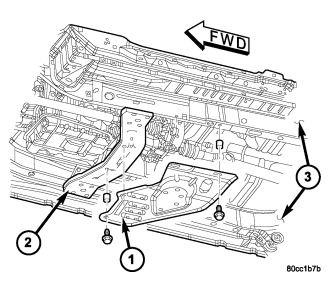
1. Shift transfer case into NEUTRAL.
2. Raise vehicle.
3. Remove skid plate (1).
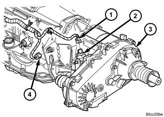
4. Drain transfer case lubricant.
5. Mark front and rear propeller shaft yokes for alignment reference.
6. Disconnect front/rear propeller shafts at transfer case.
7. Disconnect transfer case position sensor connector (1).
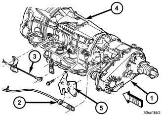
8. Disconnect transfer case shift cable (2) at the range lever.
9. Disconnect the transfer case shift cable from the shift cable bracket.
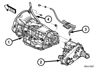
10. Disconnect transfer case vent hose (3).
11. Support transfer case with transmission jack.
12. Secure transfer case to jack with chains.
13. Remove nuts attaching transfer case to transmission.
14. Pull transfer case and jack rearward to disengage transfer case.
15. Remove transfer case from under vehicle.
DISASSEMBLY
REAR RETAINER
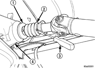
1. Remove output shaft boot (2). Spread band clamp that secures boot on slinger with a suitable awl. Then slide boot off shaft.
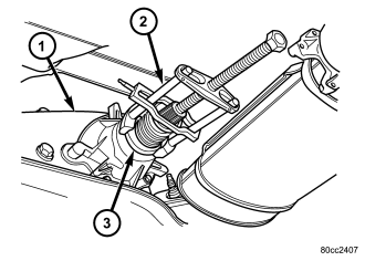
2. Using puller MD-998056-A (2), remove rear slinger (3).
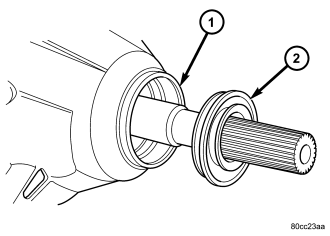
3. Remove rear seal (2) from retainer (1). Use pry tool, or collapse seal with punch to remove it.
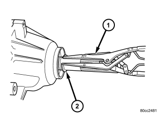
4. Remove rear output bearing I.D. retaining ring (2).
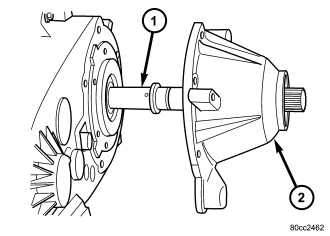
5. Remove rear retainer bolts.
6. Remove rear retainer (2). Tap retainer with mallet and pry upward to break sealer bead. Then slide retainer off case and output shaft.
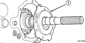
7. Remove rear bearing O.D. retaining ring with snap-ring pliers. Then tilt oil pump (1) and slide it off output shaft.
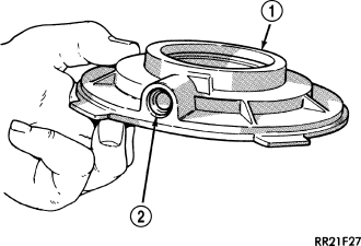
8. Remove pickup tube O-ring (2) from pump (1) but do not disassemble pump; it is not a serviceable part.
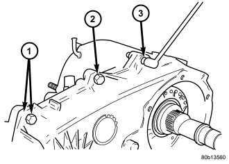
9. Remove bolts (2) attaching rear case to front case. Note position of the two black finish bolts (1) at each end of the case. These bolts go through the case dowels and require a washer under the bolt head.
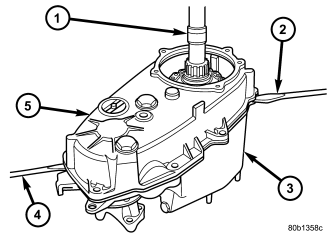
CAUTION: Do not pry on the sealing surface of either case half as the surfaces will become damaged.
10. Remove rear case (5) from front case (3). Insert screwdrivers into slots cast into each end of case. Then pry upward to break sealer bead and remove rear case.
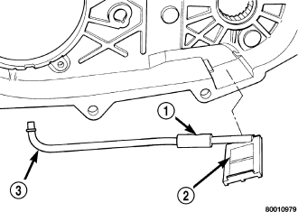
11. Remove oil pickup tube (3) and screen (2) from rear case.
COMPANION FLANGE AND RANGE LEVER
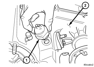
1. Remove transfer case position sensor (1).
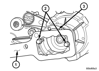
2. Install two bolts (2) partially into the propeller shaft companion flange, 180° from each other.
3. Install the rectangular end of the Flange Holder C-3281 (1) over the bolts to hold the companion flange (3) stationary and remove the nut holding the companion flange to the output shaft.

4. Use Remover C-452 (3) to remove the companion flange (2).
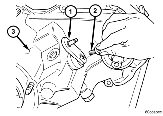
NOTE: Be sure to note the orientation of the range lever (lever up or down) so that it may be re-installed in the same direction.
5. Remove seal washer from front output shaft. Discard washer as it should not be reused.
6. Remove the bolt (2) that attaches the range lever (1) to sector shaft. Then move sector to neutral position and remove range lever from shaft.
FRONT OUTPUT SHAFT AND DRIVE CHAIN
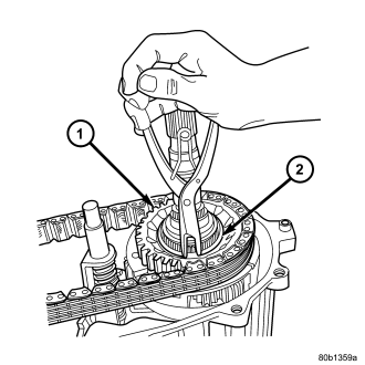
1. Remove drive sprocket (1) snap-ring (2).

2. Remove drive sprocket (1) and chain (2).
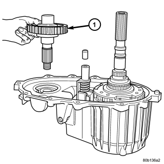
3. Remove front output shaft (1).
SHIFT FORKS AND MAINSHAFT
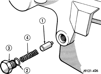
1. Remove shift detent plug (3), spring (4), and plunger (1).
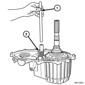
2. Remove seal plug from low range fork lockpin access hole. Then move shift sector to align low range fork lockpin with access hole.
3. Remove range fork lockpin with size number one easy-out tool as follows:
a. Insert easy-out tool through access hole in side of transfer case and into lock-pin.
b. Tap easy-out tool into lock-pin with hammer until tool is securely engaged into the lock-pin.
c. Install a t-handle, such as from a tap and die set, onto the easy-out tool.
d. Securely tighten the t-handle onto the tool.
e. In one motion, pull upward and turn the t-handle counter-clockwise to remove the lock-pin.
4. Remove shift rail (1) by pulling it straight up and out of fork (2).
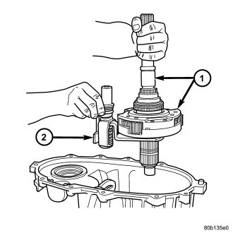
5. Remove mode fork (2) and mainshaft as assembly (1).
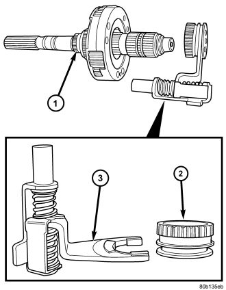
6. Remove mode shift sleeve (2) and mode fork assembly (3) from mainshaft (1). Note position of mode sleeve in fork and remove sleeve.
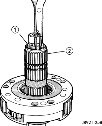
7. Remove intermediate clutch shaft (2) snap-ring (1).
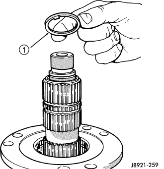
8. Remove clutch shaft thrust ring (1).
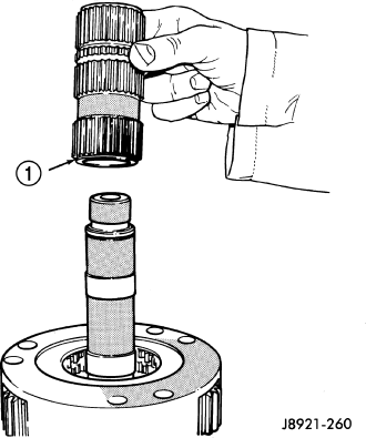
9. Remove intermediate clutch shaft (1).
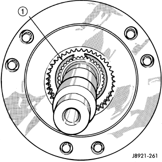
10. Remove differential snap-ring (1).
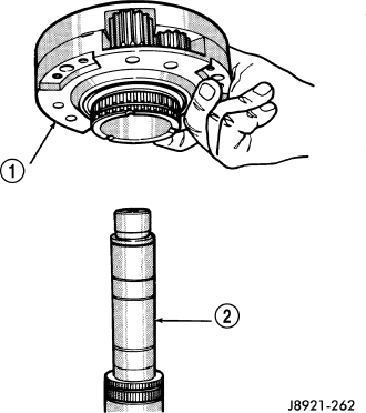
11. Remove differential (1).
12. Remove differential needle bearings and both needle bearing thrust washers from mainshaft.
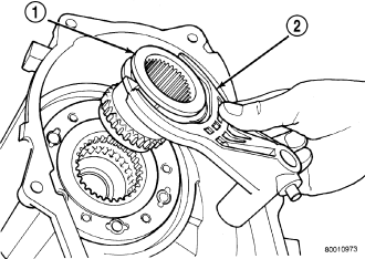
13. Slide low range fork pin out of shift sector slot.
14. Remove low range fork (2) and hub (1).
15. Remove shift sector.
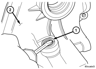
16. Remove the shift sector shaft seal (1).
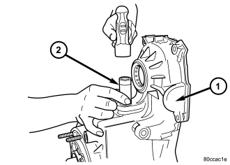
17. Remove the shift sector shaft bearing with an appropriate socket (2).
INPUT GEAR/LOW RANGE ASSEMBLY
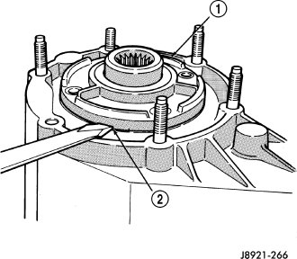
1. Remove front bearing retainer bolts.
2. Remove front bearing retainer (1). Carefully pry retainer loose with screwdriver. Position screwdriver in slots (2) cast into retainer.
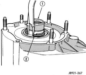
3. Remove input gear snap-ring (2).
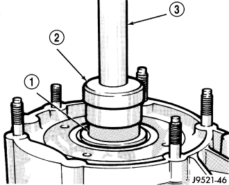
4. Remove input/low range gear assembly from bearing with Universal Handle C-4171 (3) and Tool 7829-A (2).
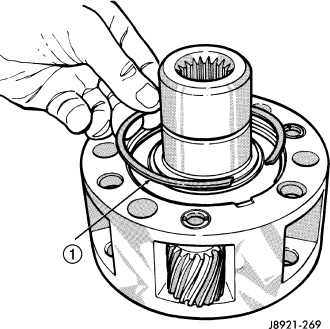
5. Remove low range gear snap-ring (1).
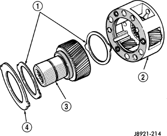
6. Remove input gear retainer, thrust washers (1), and input gear (3) from low range gear (2).
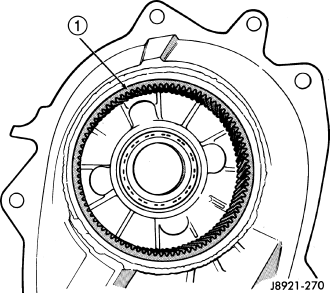
7. Inspect low range annulus gear (1). The annulus gear is not a serviceable component. If damaged, replace gear and front case as assembly.
8. Remove oil seals from following components:
- front bearing retainer.
- rear retainer.
- oil pump.
- case halves.
DIFFERENTIAL
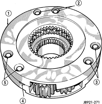
1. Mark differential case halves for reference.
2. Remove differential case bolts.
3. Invert differential on workbench.
4. Separate top case (1) from bottom case. Use slots in case halves to pry them apart.
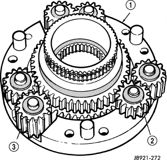
5. Remove thrust washers (2) and planet gears (3) from case pins.
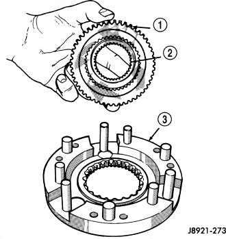
6. Remove mainshaft (1) and sprocket (2) gears from bottom case (3). Note gear position for reference before separating them.
CLEANING
Clean the transfer case parts with a standard parts cleaning solvent. Remove all traces of sealer from the cases and retainers with a scraper and all purpose cleaner. Use compressed air to remove solvent residue from oil feed passages in the case halves, retainers, gears, and shafts.
The oil pickup screen can be cleaned with solvent. Shake excess solvent from the screen after cleaning and allow it to air dry. Do not use compressed air.
INSPECTION
MAINSHAFT/SPROCKET/HUB
Inspect the splines on the hub and shaft and the teeth on the sprocket. Minor nicks and scratches can be smoothed with an oilstone. However, replace any part that is damaged.
Check the contact surfaces in the sprocket bore and on the mainshaft. Minor nicks and scratches can be smoothed with 320-400 grit emery cloth but do not try to salvage the shaft if nicks or wear is severe.
INPUT GEAR AND PLANETARY CARRIER
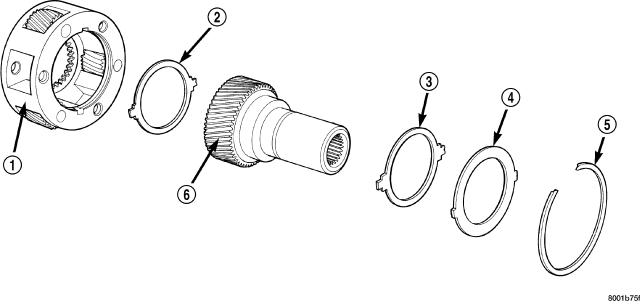
Check the teeth on the gear (6). Minor nicks can be dressed off with an oilstone but replace the gear if any teeth are broken, cracked, or chipped. The bearing surface on the gear can be smoothed with 300-400 grit emery cloth if necessary.
Examine the carrier body (1) and pinion gears for wear or damage. The carrier will have to be replaced as an assembly if the body, pinion pins, or pinion gears are damaged.
Check the lock ring (4) and both thrust washers (2, 3) for wear or cracks. Replace them if necessary. Also replace the lock retaining ring if bent, distorted, or broken.
SHIFT FORKS/HUBS/SLEEVES
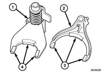
Check condition of the shift forks and mode fork shift rail (1). Minor nicks on the shift rail can be smoothed with 320-400 grit emery cloth.
Inspect the shift fork wear pads. The mode fork pads (4) are serviceable and can be replaced if necessary. The range fork pads (3) are also serviceable.
Check both of the sleeves for wear or damage, especially on the interior teeth. Replace the sleeves if wear or damage is evident.
REAR RETAINER/BEARING/ SEAL/SLINGER/BOOT
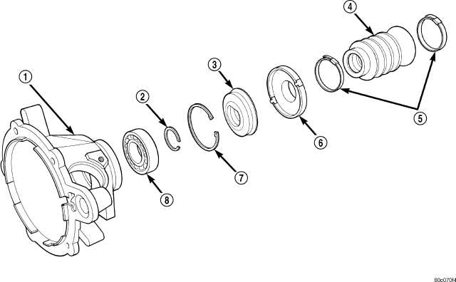
Inspect the retainer components. Replace the bearing (8) if rough or noisy. Check the retainer (1) for cracks or wear in the bearing bore. Clean the retainer sealing surfaces with a scraper and 3M all purpose cleaner. This will ensure proper adhesion of the sealer during reassembly.
Replace the slinger (6) and seal (3) outright; do not reuse either part.
Replace any part if distorted, bent, or broken. Also replace the boot if cut or torn. Replace the boot band clamps, do not reuse them.
REAR OUTPUT SHAFT/YOKE/DRIVE CHAIN
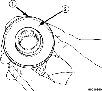
Check condition of the seal contact surfaces (2) of the yoke slinger (1). This surface must be clean and smooth to ensure proper seal life. Replace the yoke nut and seal washer as neither part should be reused.
Inspect the shaft threads, sprocket teeth, and bearing surfaces. Minor nicks on the teeth can be smoothed with an oilstone. Use 320-400 grit emery to smooth minor scratches on the shaft bearing surfaces. Rough threads on the shaft can be chased if necessary. Replace the shaft if the threads are damaged, bearing surfaces are scored, or if any sprocket teeth are cracked or broken.
Examine the drive chain and shaft bearings. Replace the chain and both sprockets if the chain is stretched, distorted, or if any of the links bind. Replace the bearings if rough, or noisy.
LOW RANGE ANNULUS GEAR
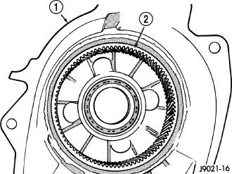
Inspect annulus gear condition carefully. The gear is only serviced as part of the front case. If the gear is damaged, it will be necessary to replace the gear and front case as an assembly. Do not attempt to remove the gear (2)
FRONT-REAR CASES AND FRONT RETAINER
Inspect the cases and retainer for wear and damage. Clean the sealing surfaces with a scraper and 3M all purpose cleaner. This will ensure proper sealer adhesion at assembly. Replace the input retainer seal; do not reuse it.
Check case condition. If leaks were a problem, look for gouges and severe scoring of case sealing surfaces. Also make sure the front case mounting studs are in good condition.
Check the front case mounting studs and vent tube. The tube can be secured with Loctite™ 271 or 680 if loose. The stud threads can be cleaned up with a die if necessary. Also check condition of the fill/drain plug threads in the rear case. The threads can be repaired with a thread chaser or tap if necessary. Or the threads can be repaired with Helicoil™ stainless steel inserts if required.
OIL PUMP/OIL PICKUP
Examine the oil pump pickup parts. Replace the pump if any part appears to be worn or damaged. Do not disassemble the pump as individual parts are not available. The pump is only available as a complete assembly. The pickup screen, hose, and tube are the only serviceable parts and are available separately.
ASSEMBLY
Lubricate transfer case components with automatic transmission fluid or petroleum jelly (where indicated) during assembly.
CAUTION: The bearing bores in various transfer case components contain oil feed holes. Make sure replacement bearings do not block the holes.
BEARINGS AND SEALS
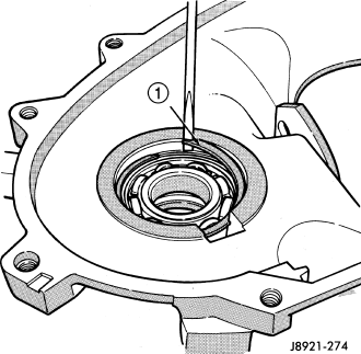
1. Remove snap-ring (1) that retains front output shaft front bearing in case. Then remove bearing. Use hammer handle, or hammer and brass punch to tap bearing out of case.
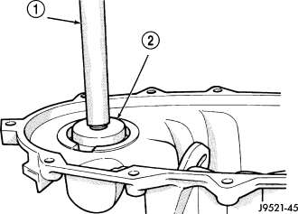
2. Install new front output shaft front bearing with Tool Handle C-4171 (1) and Installer 8033-A (2) with the tapered cone upward.
3. Install front bearing snap-ring.
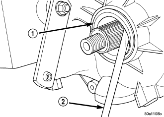
4. Remove front output shaft seal (1) using an appropriate pry tool (2) or slide-hammer mounted screw.
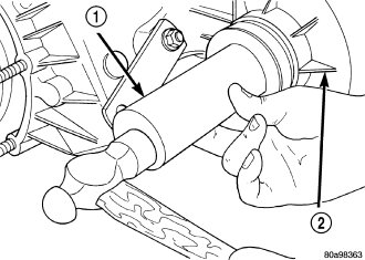
5. Install new front output shaft oil seal with Installer 6952-A (1).
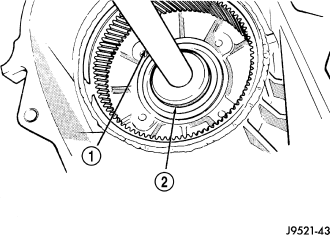
6. Remove input gear bearing with Tool Handle C-4171 (1) and Remover C-4210 (2).
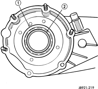
7. Install snap-ring on new input gear bearing.
8. Install new input gear bearing (2) with Tool Handle C-4171 and Remover C-4210. Install bearing far enough to seat snap-ring (1) against case.
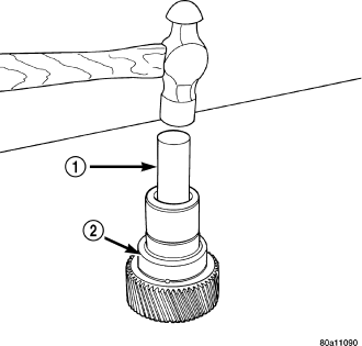
9. Remove the input gear pilot bearing by inserting a suitably sized drift (1) into the splined end of the input gear (2) and driving the bearing out with the drift and a hammer.
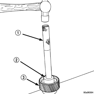
10. Install new pilot bearing with Installer 8128 (2) and Handle C-4171 (1).
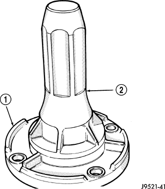
11. Install new seal in front bearing retainer (1) with Installer 7884 (2).
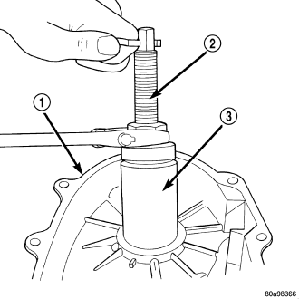
12. Remove output shaft rear bearing with the screw and jaws from Remover L-4454 (2) and Cup 8148 (3).
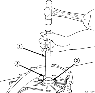
13. Install new bearing with Tool Handle C-4171 (1) and Installer 5066 (3). Lubricate bearing after installation.
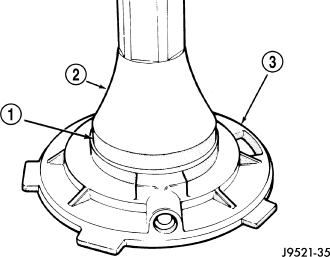
14. Install new seal in oil pump feed housing (3) with Special Tool 7888 (2).
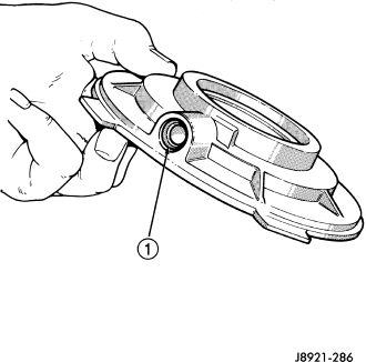
15. Install new pickup tube O-ring (1) in oil pump.
DIFFERENTIAL
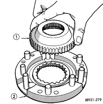
1. Lubricate differential components with automatic transmission fluid.
2. Install sprocket gear (1) in differential bottom case (2).
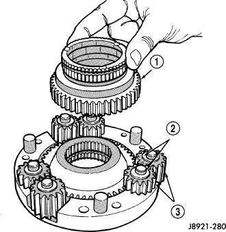
3. Install differential planet gears (3) and new thrust washers (2). Be sure thrust washers are installed at top and bottom of each planet gear.
4. Install differential mainshaft gear (1).
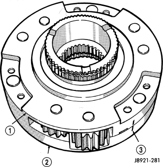
5. Align and position differential top case (1) on bottom case (2). Align using scribe marks (3) made at disassembly.
6. While holding differential case halves together, invert the differential and start the differential case bolts.
7. Tighten differential case bolts to specified torque.
INPUT GEAR/LOW RANGE ASSEMBLY
1. Assemble low range gear (2), input gear thrust washers, input gear (3), and input gear retainer (4).
2. Install low range gear snap-ring (1).
3. Lubricate input gear and low range gears with automatic transmission fluid.
4. Start input gear shaft into front case bearing.
5. Press input gear shaft into front bearing.
6. Install new input gear snap ring (2).
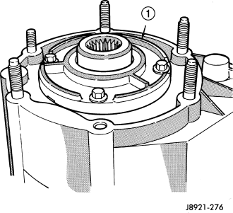
7. Apply 3 mm (1/8 in.) wide bead of Mopar® gasket maker or silicone adhesive sealer to seal surface of front bearing retainer.
8. Install front bearing retainer (1). Tighten retainer bolts to 16 ft. lbs. (21 N·m) torque.
SHIFT FORKS, SECTOR, AND MAINSHAFT
1. Install the shift sector shaft bearing using a suitable socket (2) until the bearing is flush to the bottom, inner edge of the bore.
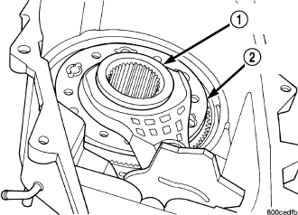
2. Install a new shift sector shaft seal using a suitable socket until the seal is flush to the bottom of the bore lead-in chamfer.
3. Install shift sector.
4. Install new pads on low range fork, if necessary.
5. Assemble low range fork and sleeve.
6. Position low range fork (2) and hub (1) in case. Be sure low range fork pin is engaged in shift sector slot.
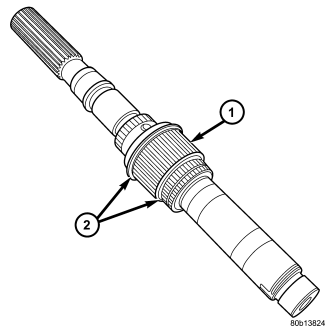
7. Install first mainshaft bearing spacer (2) on mainshaft.
8. Install bearing rollers on mainshaft. Coat bearing rollers with generous quantity of petroleum jelly to hold them in place.
9. Install remaining bearing spacer on mainshaft. Do not displace any bearings while installing spacer.
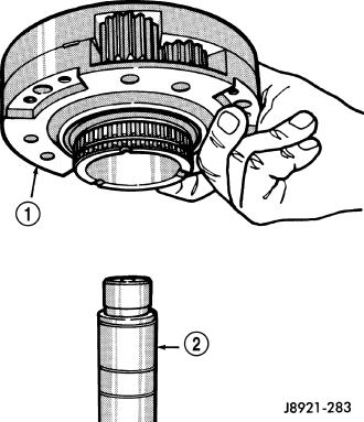
10. Install differential (1). Do not displace mainshaft bearings when installing differential.
11. Install differential snap-ring (1).
12. Install intermediate clutch shaft (1).
13. Install clutch shaft thrust washer (1).
14. Install clutch shaft (2) snap-ring (1).
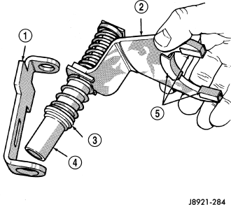
15. Inspect mode fork assembly. Replace pads (5) and bushing (3), if necessary. Replace fork tube (4) if bushings inside tube are worn or damaged. Also check springs (3) and slider bracket. Replace worn, damaged components.
16. Install mode sleeve (2) in mode fork (3). Then install assembled sleeve and fork on mainshaft. Be sure mode sleeve splines are engaged in differential splines.
17. Install mode fork (2) and mainshaft assembly (1) in case. Rotate mainshaft slightly to engage shaft with low range gears.
18. Rotate mode fork pin into shift sector slot.
19. Install shift rail (1). Be sure rail is seated in both shift forks.
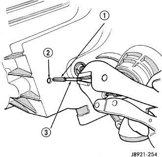
20. Rotate shift sector to align lockpin hole in low range fork with access hole in case.
21. Insert an easy-out (3) in range fork lockpin (1) to hold it securely for installation. Lockpin is slightly tapered on one end. Insert tapered end into fork and rail.
22. Insert lockpin through access hole and into shift fork. Then remove easy-out and seat the pin with pin punch.
23. Install plug in lockpin access hole.
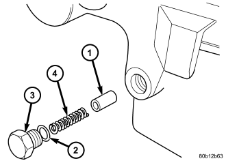
24. Install detent plunger (1), detent spring (4), and detent plug (3) in case.
FRONT OUTPUT SHAFT AND DRIVE CHAIN
1. Install front output shaft.
2. Install drive chain (2). Engage chain with front output shaft sprocket teeth.
3. Install drive sprocket (1). Engage drive sprocket teeth with chain. Then engage sprocket splines with mainshaft splines.
4. Install drive sprocket (1) snap-ring (2).
OIL PUMP AND REAR CASE
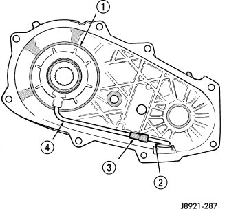
1. Insert oil pickup tube (4) in oil pump (1) and attach oil screen (2) and connector hose (3) to pickup tube. Then install assembled pump, tube and screen in rear case. Be sure screen is seated in case slot as shown.
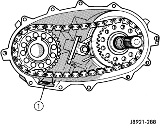
2. Install magnet in front case pocket .
3. Apply 3 mm (1/8 in.) wide bead of Mopar® gasket maker or silicone adhesive sealer to seal surface of front case.
4. Align and install rear case on front case. Be sure case locating dowels are in place and that mainshaft splines are engaged in oil pump inner gear.
5. Install and tighten front case-to-rear case bolts to 41 N·m (30 ft. lbs.) torque. Be sure to install a washer under each bolt used at case dowel locations.
REAR RETAINER
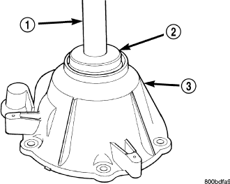
1. Remove rear bearing in retainer using Installer 8128 and Handle C-4171.
2. Install rear bearing in retainer with Tools C-4171 (1) and 5064 (2).
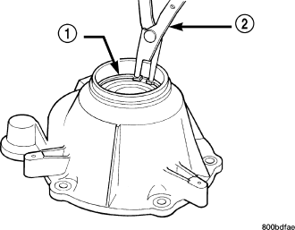
3. Install rear bearing O.D. retaining ring (1) with snap-ring pliers (2). Be sure retaining ring is fully seated in retainer groove.
4. Apply bead of Mopar® Sealer P/N 82300234, or Loctite™ Ultra Gray, to mating surface of rear retainer. Sealer bead should be a maximum of 3/16 in.
5. Install rear retainer on rear case. Tighten retainer bolts to 20-27 N·m (15-20 ft. lbs.) torque.
6. Install rear bearing I.D. retaining ring and spacer on output shaft.
7. Apply liberal quantity of petroleum jelly to new rear seal and to output shaft. Petroleum jelly is needed to protect seal lips during installation.
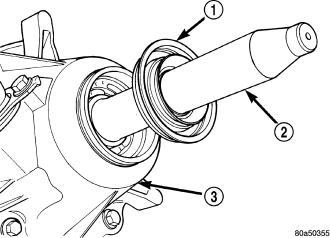
8. Slide seal onto Seal Protector 8824 (2). Slide seal protector and seal (1) onto output shaft.
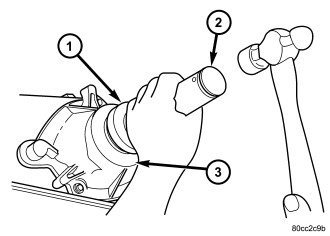
9. Slide Installer 8691 (1) onto seal protector with the recessed side of the tool toward the seal. Drive seal into rear bearing retainer with Installer 8691.
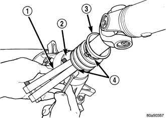
10. Install rear slinger with Installer 9023.
11. Install boot (3) on output shaft slinger (2) and crimp retaining clamp (4) with tool C-4975-A (1).
COMPANION FLANGE AND RANGE LEVER
1. Install range lever (1) and bolt (2) on sector shaft. Tighten bolt to 27-34 N·m (20-25 ft. lbs.) torque.
2. Inspect the o-ring on the transfer case position sensor. Replace the o-ring if necessary.
3. Install the transfer case position sensor (1) in the front case (2). Tighten sensor to 20-34 N·m (15-25 ft. lbs.) torque.
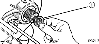
4. Install new seal washer (1) on front output shaft.
5. Lubricate companion flange hub with transmission fluid and install flange onto the front ouput shaft.
6. Install new seal washer on front shaft.
7. Install new flange nut onto front output shaft.
8. Tighten flange nut to 122-176 N·m (90-130 ft. lbs.) torque.
INSTALLATION
1. Mount transfer case on a transmission jack.
2. Secure transfer case to jack with chains.
3. Position transfer case under vehicle.
4. Align transfer case and transmission shafts and install transfer case on transmission.
5. Install and tighten transfer case attaching nuts to 35 N·m (26 ft. lbs.) torque.
6. Connect vent hose.
7. Connect transfer case position sensor connector to sensor.
8. Align and connect propeller shafts. (Refer to 3 - DIFFERENTIAL & DRIVELINE/PROPELLER SHAFT/PROPELLER SHAFT - INSTALLATION) .
9. Fill transfer case with correct fluid. Check transmission fluid level. Correct as necessary.
10. Install skid plate. (Refer to 13 - FRAME & BUMPERS/FRAME/TRANSFER CASE SKID PLATE - INSTALLATION)
11. Remove transmission jack and support stand.
12. Connect shift cable to transfer case range lever.
13. Lower vehicle and verify transfer case shift operation.