DIAGNOSIS AND TESTING
- ASBS INTERMITTENT CONDITION
- C2100-BATTERY VOLTAGE LOW
- C2101-BATTERY VOLTAGE HIGH
- C2207-OFF-ROAD ECU INTERNAL
- U0146-LOST COMMUNICATION WITH CENTRAL GATEWAY
- U0121-LOST COMMUNICATION WITH ANTI-LOCK BRAKE MODULE
- U0415-IMPLAUSIBLE DATA RECEIVED FROM ABS
- U0447-IMPLAUSIBLE DATA RECEIVED FROM CENTRAL GATEWAY
ASBS INTERMITTENT CONDITION
For a complete wiring diagram Refer to Section 8W.
Diagnostic Test
1. PERFORM ASBS INTERMITTENT CONDITION TESTNOTE: The conditions that set the DTC are not present at this time. The following list may help in identifying the intermittent condition.
WARNING: When the engine is operating, do not stand in direct line with the fan. Do not put your hands near the pulleys, belts, or fan. Do not wear loose clothing. Failure to follow these instructions can result in personal injury or death.
Refer to any Technical Service Bulletins (TSBs) that may apply.
Review the scan tool Environmental Data (EV Data). If possible, try to duplicate the conditions under which the DTC set.
Turn the ignition off.
Visually inspect the related wire harness. Disconnect all the related harness connectors. Look for any chafed, pierced, pinched, partially broken wires and broken, bent, pushed out, or corroded terminals.
Wiggle the wires while checking for shorts and open circuits.
Perform a voltage drop test on the related circuits between the suspected faulty component and the Automatic Sway-Bar System.
Inspect and clean all PCM, ASBS, engine, and chassis grounds that are related to the most current DTC.
If numerous trouble codes were set, use a wire schematic and look for any common ground or supply circuits
For any Relay DTCs, actuate the Relay with the scan tool and wiggle the related wire harness to try to interrupt the actuation.
Use the scan tool to perform a System Test if one applies to failing component.
A co-pilot, data recorder, and/or lab scope should be used to help diagnose intermittent conditions.
Were any problems found during the above inspections?
Yes
- Perform the necessary repairs.
- Perform ASBS VERIFICATION TEST. (Refer to 2 - SUSPENSION/ACTIVE CHASSIS - STANDARD PROCEDURE)
No
- Test Complete.
C2100-BATTERY VOLTAGE LOW
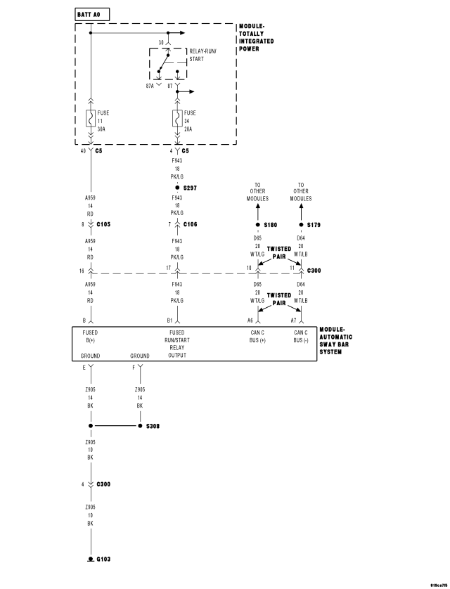
For a complete wiring diagram Refer to Section 8W
- When Monitored:
Continuously.
- Set Condition:
The Automatic Sway-Bar System detects that system voltage is below 9.0 volts for 60 seconds.
| Possible Causes |
| INTERMITTENT BATTERY VOLTAGE LOW |
| CHARGING SYSTEM DTCS PRESENT |
| (A959) FUSED B+ CIRCUIT OPEN OR HIGH RESISTANCE |
| AUTOMATIC SWAY-BAR SYSTEM (ASBS) |
Diagnostic Test
1. CHARGING SYSTEM DTCS PRESENTIgnition on.
With the scan tool, select View DTCs in the Powertrain Control Module.
Are there any Charging System or related voltage DTCs present?
Yes
- Refer to the symptom list and perform any Charging System DTC diagnostic procedures before continuing with this test.
No
- Go to 2
2. DTC IS ACTIVE
With the scan tool, select View DTCs in the ASBS.
Is the status Active for this DTC?
Yes
- Go to 3
No
- Go to 5
3. (A959) FUSED B+ CIRCUIT OPEN OR HIGH RESISTANCE
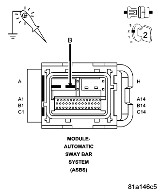
Turn the ignition off.
Disconnect the ASBS harness connector.
Turn the ignition on.
With a 12–volt test light connected to ground, check the (A959) Fused B+ circuit in the ASBS harness connector.
NOTE: The test light must illuminate brightly. Compare the brightness to that of a direct connection to the battery.
Does the test light illuminate brightly?
Yes
- Go to 4
No
- Repair the (A959) Fused B+ circuit for an open circuit or high resistance.
- Perform ASBS VERIFICATION TEST. (Refer to 2 - SUSPENSION/ACTIVE CHASSIS - STANDARD PROCEDURE)
4. AUTOMATIC SWAY-BAR SYSTEM (ASBS)
View repair.
Repair
- Replace the Automatic Sway-Bar System Module in accordance with the Service information.
- Perform ASBS VERIFICATION TEST. (Refer to 2 - SUSPENSION/ACTIVE CHASSIS - STANDARD PROCEDURE)
5. INTERMITTENT WIRING AND CONNECTORS
The conditions necessary to set this DTC are not present at this time.
Using the wiring diagram/schematic as a guide, inspect the wiring and connectors.
While monitoring the scan tool data relative to this circuit, wiggle test the wiring and connectors.
Look for the data to change or for the DTC to reset during the wiggle test.
Were any problems found?
Yes
- Repair as necessary.
- Perform ASBS VERIFICATION TEST. (Refer to 2 - SUSPENSION/ACTIVE CHASSIS - STANDARD PROCEDURE)
No
- Test complete.
C2101-BATTERY VOLTAGE HIGH
For a complete wiring diagram Refer to Section 8W
- When Monitored:
Continuously.
- Set Condition:
The Automatic Sway-Bar System detects that system voltage is above 16.0 volts for 10 seconds with engine RPM greater than 350.
| Possible Causes |
| INTERMITTENT BATTERY VOLTAGE HIGH |
| CHARGING SYSTEM DTCS PRESENT |
| AUTOMATIC SWAY-BAR SYSTEM POWER CIRCUITS OPEN OR HIGH RESISTANCE |
| AUTOMATIC SWAY-BAR SYSTEM (ASBS) |
Diagnostic Test
1. CHARGING SYSTEM DTCS PRESENTIgnition on.
With the scan tool, select View DTCs in the Powertrain Control Module.
Are there any Charging System or related voltage DTCs present?
Yes
- Refer to the symptom list and perform any Charging System DTC diagnostic procedures before continuing with this test.
No
- Go to 2
2. DTC IS ACTIVE
With the scan tool, select View DTCs in the ASBS Module.
Is the status Active for this DTC?
Yes
- Go to 3
No
- Go to 5
3. AUTOMATIC SWAY-BAR SYSTEM (ASBS) MODULE GROUND CIRCUITS OPEN OR HIGH RESISTANCE
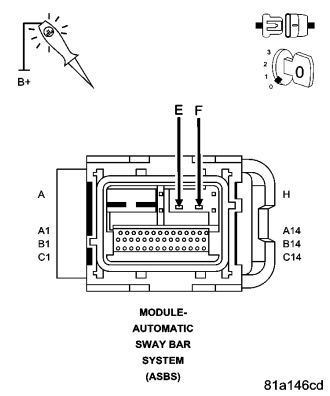
Turn the ignition off.
Disconnect the ASBS harness connector.
With a 12–volt test light connected to B+, check the Ground circuits in the ASBS harness connector.
NOTE: The test light must illuminate brightly. Compare the brightness to that of a direct connection to the battery.
Does the test light illuminate brightly for each of the Ground circuits?
Yes
- Go to 4
No
- Repair the Ground circuit(s) for an open circuit or high resistance.
- Perform ASBS VERIFICATION TEST. (Refer to 2 - SUSPENSION/ACTIVE CHASSIS - STANDARD PROCEDURE)
4. AUTOMATIC SWAY-BAR SYSTEM (ASBS) MODULE
View repair.
Repair
- Replace the ASBS Module in accordance with the Service information.
- Perform ASBS VERIFICATION TEST. (Refer to 2 - SUSPENSION/ACTIVE CHASSIS - STANDARD PROCEDURE)
5. INTERMITTENT WIRING AND CONNECTORS
The conditions necessary to set this DTC are not present at this time.
Using the wiring diagram/schematic as a guide, inspect the wiring and connectors.
While monitoring the scan tool data relative to this circuit, wiggle test the wiring and connectors.
Look for the data to change or for the DTC to reset during the wiggle test.
Were any problems found?
Yes
- Repair as necessary.
- Perform ASBS VERIFICATION TEST. (Refer to 2 - SUSPENSION/ACTIVE CHASSIS - STANDARD PROCEDURE)
No
- Test complete.
C2207-OFF-ROAD ECU INTERNAL
For a complete wiring diagram Refer to Section 8W.
- When Monitored:
Ignition on. The Automatic Sway-Bar System Module monitors its internal microprocessors for correct operation.
- Set Condition:
If the Automatic Sway-Bar System Module detects an internal fault, the DTC is set.
| Possible Causes |
| ASBS - INTERNAL FAULT |
Diagnostic Test
1. ASBS INTERNAL FAILURE DTC PRESENTTurn the ignition on.
With the scan tool, read DTCs.
With the scan tool, erase DTCs.
Cycle the ignition switch.
With the scan tool, read DTCs.
Does the scan tool display ASBS INTERNAL FAILURE?
Yes
- Replace the Automatic Sway-Bar System Module in accordance with the Service information.
- Perform ASBS VERIFICATION TEST. (Refer to 2 - SUSPENSION/ACTIVE CHASSIS - STANDARD PROCEDURE)
No
- Perform the ASBS Intermittent Condition diagnostic procedure in this Section.
- Refer to the ASBS INTERMITTENT CONDITION TEST. (Refer to 2 - SUSPENSION/ACTIVE CHASSIS - DIAGNOSIS AND TESTING).
U0146-LOST COMMUNICATION WITH CENTRAL GATEWAY
For a complete wiring diagram Refer to Section 8W.
- When Monitored:
- With the ignition on
- Battery voltage between 10 and 16 volts
- IOD fuse installed
- Set Condition:
If the Automatic Sway-Bar System Module either fails to receive bus messages from the Engine Control Module (ECM) for approximately 500 ms, or it receives invalid messages from the ECM, or it detects messages from the ECM are of improper data length.
| Possible Causes |
| DTCs RELATED TO BATTERY VOLTAGE, IGNITION, OR VIN MESSAGES |
| CAN C BUS CIRCUITS OPEN OR SHORTED |
| ECM POWER AND GROUND |
| ECM |
| AUTOMATIC SWAY-BAR SYSTEM (ASBS) MODULE |
Diagnostic Test
1. VERIFY DTC IS ACTIVENOTE: Ensure the IOD fuse is installed and battery voltage is between 10 and 16 volts before proceeding.
Turn the ignition on.
With the scan tool, read and record ASBS DTCs.
With the scan tool, read and record Environmental Data (EV Data).
With the scan tool, erase ASBS DTCs.
Cycle the ignition switch.
With the scan tool, read ASBS DTCs.
Does this DTC reset?
Yes
- Go To 2
No
- The condition that caused the symptom is currently not present. Inspect the related wiring for a possible intermittent condition. Look for any chafed, pierced, pinched, or partially broken wires.
- Perform ASBS VERIFICATION TEST. (Refer to 2 - SUSPENSION/ACTIVE CHASSIS - STANDARD PROCEDURE)
2. CHECK FOR ANY OF THE FOLLOWING ACTIVE DTCs
With the scan tool, read all active DTCs from all CAN C Bus modules.
NOTE: Check for CAN C hardware electrical, VIN Missing/Mismatch, battery or ignition related DTCs.
Does the scan tool display any active DTCs related to the conditions listed above?
Yes
- Diagnose and repair the DTC(s). Refer to the Table of Contents in the applicable Section.
- Perform BODY VERIFICATION TEST – VER 1. (Refer to 8 - ELECTRICAL/ELECTRONIC CONTROL MODULES - STANDARD PROCEDURE).
No
- Go To 3
3. VERIFY THAT THE ECM IS ACTIVE ON THE BUS
With the scan tool, select ECU View.
Verify that the ECM is active on the bus.
Is the ECM active on the bus?
Yes
- Go To 4
No
- Perform the Stored Lost Communication test procedure.
- Perform BODY VERIFICATION TEST – VER 1. (Refer to 8 - ELECTRICAL/ELECTRONIC CONTROL MODULES - STANDARD PROCEDURE).
4. CHECK FOR ADDITIONAL COMMUNICATION RELATED DTCs
With the scan tool, select Network View and select Advanced.
Is there more than one module with active DTCs “Logged Against” the ECM?
Yes
- Replace/update the ECM in accordance with the service information.
No
- Replace and program the Final Drive Control Module in accordance with Service Information.
- Perform ASBS VERIFICATION TEST. (Refer to 2 - SUSPENSION/ACTIVE CHASSIS - STANDARD PROCEDURE)
U0121-LOST COMMUNICATION WITH ANTI-LOCK BRAKE MODULE
For a complete wiring diagram Refer to Section 8W.
- When Monitored:
Ignition run time is greater than 1 second. Battery voltage between 10 and 16 volts. Engine run time greater than 3 seconds.
- Set Condition:
The PCM doesn't receive an ABS message over the CAN C circuit for 7 consecutive seconds. The circuit is continuously monitored. One Trip fault.
| Possible Causes |
| CAN C BUS OPEN OR SHORTED CONDITION |
| ABS MODULE |
| TIPM |
| PCM |
Refer to 8 - ELECTRICAL/ELECTRONIC CONTROL MODULES - DIAGNOSIS AND TESTING for diagnostic procedures and for further possible causes.
Diagnostic Test
1. ACTIVE DTCIgnition on, engine not running.
With a scan tool, select View PCM DTCs.
Is the DTC Active at this time?
Yes
- Refer to 8 - ELECTRICAL/ELECTRONIC CONTROL MODULES - DIAGNOSIS AND TESTING for diagnostic procedures and for further possible causes.
No
- Refer to the INTERMITTENT CONDITION Diagnostic Procedure.
- Perform the POWERTRAIN VERIFICATION TEST. (Refer to 9 - ENGINE - STANDARD PROCEDURE)
U0415-IMPLAUSIBLE DATA RECEIVED FROM ABS
For a complete wiring diagram Refer to Section 8W
- When Monitored:
With the ignition on for 4 seconds, no CAN BUS circuit error condition present, no lost communication with ABS condition present, and no system undervoltage or overvoltage condition present.
- Set Condition:
The Automatic Sway-Bar System Module is receiving implausible data for vehicle speed, wheel speed.
| Possible Causes |
| ANTILOCK BRAKE SYSTEM DTCS PRESENT |
| AUTOMATIC SWAY-BAR SYSTEM (ASBS) |
Diagnostic Test
1. ABS DTCS PRESENTIgnition on, engine not running.
With the scan tool, read DTCs in the Antilock Brake Controller.
Are there any DTCs present?
Yes
- Refer to the symptom list and perform the applicable diagnostic procedure.
- Perform ASBS VERIFICATION TEST. (Refer to 2 - SUSPENSION/ACTIVE CHASSIS - STANDARD PROCEDURE)
No
- Replace the ASBS Module in accordance with the Service Information.
- Perform ASBS VERIFICATION TEST. (Refer to 2 - SUSPENSION/ACTIVE CHASSIS - STANDARD PROCEDURE)
U0447-IMPLAUSIBLE DATA RECEIVED FROM CENTRAL GATEWAY
For a complete wiring diagram Refer to Section 8W
- When Monitored:
Continuously with the ignition on, one valid CAN message received at least once, and no U0002-CAN C Bus Off Performance DTC present.
- Set Condition:
When the Automatic Sway-Bar System Module detects an incorrect CAN message from the Totally Integrated Power Module (TIPM).
| Possible Causes |
| ASBS CAN BUS DTCS |
| ENGINE DTCS |
| AUTOMATIC SWAY-BAR SYSTEM (ASBS) MODULE |
Diagnostic Test
1. CHECK FOR DTC U0401-IMPLAUSIBLE DATA RECEIVED FROM TIPMNOTE: This DTC must be active for the results of this test to be valid.
Turn the ignition on.
With the scan tool, record and erase DTCs.
Cycle the ignition switch from off to on.
With the scan tool, read DTCs.
Does the scan tool display: U0401-IMPLAUSIBLE DATA RECEIVED FROM ECM/PCM?
Yes
- Go To 2
No
- Perform the ASBS Intermittent Condition diagnostic procedure in this Section.
- Refer to the ASBS-INTERMITTENT CONDITION TEST. (Refer to 2 - SUSPENSION/ACTIVE CHASSIS - DIAGNOSIS AND TESTING).
Diagnostic Test
2. CHECK IF TIPM CAN BUS DTCs ARE PRESENTWith the scan tool, read TIPM DTCs.
Are there any TIPM CAN BUS DTCs present?
Yes
- Refer to the appropriate diagnostic. (Refer to 8-ELECTRICAL/ELECTRONIC CONTROL MODULES - DIAGNOSIS AND TESTING).
- Perform ASBS VERIFICATION TEST. (Refer to 2 - SUSPENSION/ACTIVE CHASSIS - STANDARD PROCEDURE)
No
- Go To 3
3. CHECK IF ENGINE DTCs ARE PRESENT
With the scan tool, read Engine DTCs.
Are there any Engine DTCs present?
Yes
- Refer to the 9 - ENGINE ELECTRICAL DIAGNOSTICS and diagnose the appropriate symptom.
- Perform ASBS VERIFICATION TEST. (Refer to 2 - SUSPENSION/ACTIVE CHASSIS - STANDARD PROCEDURE)
No
- Using the schematics as a guide, check the Automatic Sway-Bar System Module pins, terminals, and connectors for corrosion, damage, or terminal push out. Pay particular attention to all power and ground circuits. If no problems are found, replace the Final Drive Control Module in accordance with Service Information.
- Perform ASBS VERIFICATION TEST. (Refer to 2 - SUSPENSION/ACTIVE CHASSIS - STANDARD PROCEDURE)