ASSEMBLY-INPUT CLUTCH
DESCRIPTION
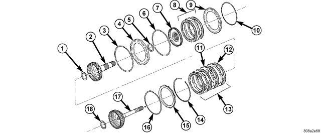
| 1 - THRUST BEARING NUMBER 3 |
10 - SNAP-RING (SELECT) |
| 2 - OD HUB/SHAFT |
11 - PLATE |
| 3 - SNAP-RING (WAVE) |
12 - DISC |
| 4 - REV/OD REACTION PLATE |
13 - OD CLUTCH |
| 5 - THRUST BEARING NUMBER 4 |
14 - SNAP-RING (TAPERED) |
| 6 - SNAP-RING (FLAT) |
15 - UD/OD REACTION PLATE |
| 7 - REVERSE HUB/SHAFT |
16 - SNAP-RING (FLAT) |
| 8 - REVERSE CLUTCH |
17 - UD HUB/SHAFT |
| 9 - REVERSE REACTION PLATE |
18 - THRUST BEARING NUMBER 2 |
Three hydraulically applied input clutches are used to drive planetary components. The underdrive, overdrive, and reverse clutches are considered input clutches and are contained within the input clutch assembly.
The input clutch assembly also contains:
- Input shaft
- Input hub
- Clutch retainer
- Underdrive piston
- Overdrive/reverse piston
- Overdrive hub
- Underdrive hub
OPERATION
The three input clutches are responsible for driving different components of the planetary geartrain.
UNDERDRIVE CLUTCH
The underdrive clutch is hydraulically applied in first, second, second prime, and third (direct) gears by pressurized fluid against the underdrive piston. When the underdrive clutch is applied, the underdrive hub drives the input sun gear.
OVERDRIVE CLUTCH
The overdrive clutch is hydraulically applied in third (direct), fourth, and fifth gears by pressurized fluid against the overdrive/reverse piston. When the overdrive clutch is applied, the overdrive hub drives the reverse carrier/input annulus assembly.
REVERSE CLUTCH
The reverse clutch is hydraulically applied in reverse gear by pressurized fluid against the overdrive/reverse piston. When the reverse clutch is applied, the reaction annulus gear is driven.
DISASSEMBLY
NOTE: If the input clutch assembly is being reconditioned (clutch/seal replacement) or replaced, it is necessary to perform the Quick Learn Procedure using the scan tool (Refer to 8 - ELECTRICAL/ELECTRONIC CONTROL MODULES/TRANSMISSION CONTROL MODULE - STANDARD PROCEDURE).
| 1 - THRUST BEARING NUMBER 3 | 10 - SNAP-RING (SELECT) |
| 2 - OD HUB/SHAFT | 11 - PLATE |
| 3 - SNAP-RING (WAVE) | 12 - DISC |
| 4 - REV/OD REACTION PLATE | 13 - OD CLUTCH |
| 5 - THRUST BEARING NUMBER 4 | 14 - SNAP-RING (TAPERED) |
| 6 - SNAP-RING (FLAT) | 15 - UD/OD REACTION PLATE |
| 7 - REVERSE HUB/SHAFT | 16 - SNAP-RING (FLAT) |
| 8 - REVERSE CLUTCH | 17 - UD HUB/SHAFT |
| 9 - REVERSE REACTION PLATE | 18 - THRUST BEARING NUMBER 2 |
1. Remove the reverse reaction plate selective snap-ring (10) from the input clutch retainer.
2. Remove the reverse reaction plate (9) from the input clutch retainer.
3. Remove the reverse hub (7) and reverse clutch pack (8) from the input clutch retainer.
4. Remove the number 4 thrust bearing (5) from the overdrive hub (2).
5. Remove the overdrive hub (2) from the input clutch retainer.
6. Remove the number 3 thrust bearing (1) from the underdrive hub (17).
7. Remove the OD/reverse pressure plate snap-ring (6) from the from the OD/reverse piston.
8. Remove the underdrive hub (17), overdrive clutch (13), and overdrive reaction plate (15) from the input clutch retainer.
NOTE: The overdrive friction discs and steel discs are thicker than the matching components in the underdrive and reverse clutches.
9. Remove the number 2 thrust bearing (18) from the input clutch hub.
10. Remove the overdrive clutch wave snap-ring (3) from the from the OD/reverse piston.
11. Remove the UD/OD reaction plate tapered snap-ring (14) from the input clutch retainer (13).
12. Remove the UD/OD reaction plate (15) from the input clutch retainer.
13. Remove the UD/OD reaction plate flat snap-ring (16) from the input clutch retainer.
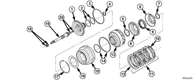
| 1 - INPUT CLUTCH HUB | 11 - UD CLUTCH |
| 2 - O-RING SEALS | 12 - PLATE |
| 3 - SEAL | 13 - CLUTCH RETAINER |
| 4 - SNAP-RING | 14 - SEAL |
| 5 - SNAP-RING | 15 - OD/REV PISTON |
| 6 - UD BALANCE PISTON | 16 - BELLEVILLE SPRING |
| 7 - SNAP-RING | 17 - SNAP-RING |
| 8 - UD PISTON | 18 - SEAL RINGS |
| 9 - SPRING | 19 - INPUT SHAFT |
| 10 - DISC | 20 - LUBRICATION CHECK VALVE AND SNAP-RING |
14. Remove the underdrive clutch pack (11) from the input clutch retainer (13).

15. Using Spring Compressor 8251 (2) , compress the UD balance piston (3) and remove the snap-ring from the input clutch hub.
| 1 - INPUT CLUTCH HUB | 11 - UD CLUTCH |
| 2 - O-RING SEALS | 12 - PLATE |
| 3 - SEAL | 13 - CLUTCH RETAINER |
| 4 - SNAP-RING | 14 - SEAL |
| 5 - SNAP-RING | 15 - OD/REV PISTON |
| 6 - UD BALANCE PISTON | 16 - BELLEVILLE SPRING |
| 7 - SNAP-RING | 17 - SNAP-RING |
| 8 - UD PISTON | 18 - SEAL RINGS |
| 9 - SPRING | 19 - INPUT SHAFT |
| 10 - DISC | 20 - LUBRICATION CHECK VALVE AND SNAP-RING |
16. Remove the UD balance piston (6) and piston return spring (9) from the input clutch retainer (13).
17. Remove the underdrive piston (8) from the input clutch retainer (13).
NOTE: Both the UD balance piston and the underdrive piston have seals molded onto them. If the seal is damaged, do not attempt to install a new seal onto the piston. The piston/seal must be replaced as an assembly.
18. Remove the input clutch retainer tapered snap-ring (5).
19. Separate input clutch retainer (13) from input clutch hub (1).
20. Separate OD/reverse piston (15) from input clutch hub retainer (13).
21. Remove all seals and o-rings from the input shaft and input hub. The o-rings on the input hub are color coded. Be sure to make note of which o-ring belongs in which location.
ASSEMBLY
| 1 - INPUT CLUTCH HUB | 11 - UD CLUTCH |
| 2 - O-RING SEALS | 12 - PLATE |
| 3 - SEAL | 13 - CLUTCH RETAINER |
| 4 - SNAP-RING | 14 - SEAL |
| 5 - SNAP-RING | 15 - OD/REV PISTON |
| 6 - UD BALANCE PISTON | 16 - BELLEVILLE SPRING |
| 7 - SNAP-RING | 17 - SNAP-RING |
| 8 - UD PISTON | 18 - SEAL RINGS |
| 9 - SPRING | 19 - INPUT SHAFT |
| 10 - DISC | 20 - LUBRICATION CHECK VALVE AND SNAP-RING |
NOTE: Install all new seals and o-rings onto the input shaft and input hub. The o-rings on the input hub are color coded. Be sure to install the correct o-ring in the correct location.
1. Check the transmission lubrication check valve (20) located in the input shaft using shop air. The valve should only allow air flow in one direction. If the valve allows no air flow, or air flow in both directions, the valve will need to be replaced.
2. Lubricate all seals with Mopar® ATF +4, Automatic Transmission Fluid, prior to installation.
3. Assemble the OD/reverse piston (15) onto the input clutch hub (1).
4. Assemble the input clutch retainer (13) onto the input clutch hub (1).
5. Install the input clutch retainer tapered snap-ring (5) with tapered side up onto the input clutch hub (1).
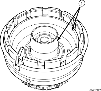
6. Install Piston Installer 8504 (1) into the input clutch retainer and onto the input clutch hub to guide the inner and outer underdrive piston seals into position.
7. Install the underdrive piston into the input clutch retainer and over the input clutch hub.
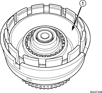
8. Install the UD balance piston return spring pack into the input clutch retainer.
9. Install Piston Installer 8252 (1) into the input clutch retainer to guide the UD balance piston seal into position inside the underdrive piston.
NOTE: The UD clutch discs can be identified by their tan color and cross-hatched groove pattern (two sets of parallel grooves at 90 degrees to each other). The UD separator plates can be identified by semi-circular cutouts on the edges of the teeth. The reverse clutch and UD clutch use common separator plates.
10. Install the UD balance piston (3) into the input clutch retainer and the underdrive piston.
11. Using Spring Compressor 8251 (2), compress the UD return spring pack and secure the piston in place with the snap-ring.
12. Install the underdrive clutch pack into the input clutch retainer.
| 1 - THRUST BEARING NUMBER 3 | 10 - SNAP-RING (SELECT) |
| 2 - OD HUB/SHAFT | 11 - PLATE |
| 3 - SNAP-RING (WAVE) | 12 - DISC |
| 4 - REV/OD REACTION PLATE | 13 - OD CLUTCH |
| 5 - THRUST BEARING NUMBER 4 | 14 - SNAP-RING (TAPERED) |
| 6 - SNAP-RING (FLAT) | 15 - UD/OD REACTION PLATE |
| 7 - REVERSE HUB/SHAFT | 16 - SNAP-RING (FLAT) |
| 8 - REVERSE CLUTCH | 17 - UD HUB/SHAFT |
| 9 - REVERSE REACTION PLATE | 18 - THRUST BEARING NUMBER 2 |
13. Install the UD reaction plate lower flat snap-ring (16) . The correct snap-ring can be identified by the two tabbed ears.
14. Install the UD reaction plate (15) into the input clutch retainer. The reaction plate is to be installed with the big step down.
15. Install the UD reaction plate upper tapered snap-ring (14) with tapered side up.
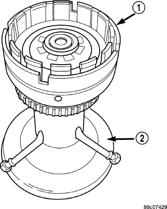
16. Install the input clutch assembly into Input Clutch Pressure Fixture 8260 (2).
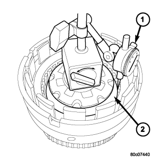
17. Mount a dial indicator C-3339A (1) on the input clutch hub. Push down on the UD clutch discs and zero the indicator against the underdrive clutch discs . Apply 20 psi of air pressure to the underdrive clutch and record the dial indicator reading. Measure and record UD clutch pack measurement in four (4) places, 90° apart. Take average of four measurements and compare with UD clutch pack clearance specification. The correct clutch clearance is 0.84-1.54 mm (0.033-0.061 in.). The reaction plate is not selective. If the clutch clearance is not within specification, replace the reaction plate along with all the friction and steel discs.
| 1 - THRUST BEARING NUMBER 3 | 10 - SNAP-RING (SELECT) |
| 2 - OD HUB/SHAFT | 11 - PLATE |
| 3 - SNAP-RING (WAVE) | 12 - DISC |
| 4 - REV/OD REACTION PLATE | 13 - OD CLUTCH |
| 5 - THRUST BEARING NUMBER 4 | 14 - SNAP-RING (TAPERED) |
| 6 - SNAP-RING (FLAT) | 15 - UD/OD REACTION PLATE |
| 7 - REVERSE HUB/SHAFT | 16 - SNAP-RING (FLAT) |
| 8 - REVERSE CLUTCH | 17 - UD HUB/SHAFT |
| 9 - REVERSE REACTION PLATE | 18 - THRUST BEARING NUMBER 2 |
18. Install the overdrive clutch pack (13) into the input clutch retainer. The overdrive steel separator plates can be identified by the lack of the half-moon cuts in the locating tabs. The OD clutch discs can be identified by their radial groove pattern.The OD clutch discs can be identified by their radial groove pattern.
19. Install the overdrive clutch wavy snap-ring (3) with the two tabbed ears into the OD/reverse piston .
20. Install the OD/reverse pressure plate (4) into the input clutch retainer. The pressure plate is non-directional.
21. Install the OD/reverse reaction plate flat snap-ring (6) into the OD/reverse piston .
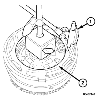
22. Mount a dial indicator C-3339A (1) on the input clutch hub and zero the indicator against the OD/reverse pressure plate (2). . Apply 20 psi of air pressure to the overdrive clutch and record the dial indicator reading. Measure and record OD clutch pack measurement in four (4) places, 90° apart. Take average of four measurements and compare with OD clutch pack clearance specification. Verify that the clutch clearance is 1.103-1.856 mm (0.043-0.073 in.). The pressure plate is not selective. If the clutch clearance is not within specification, replace the pressure plate along with all the friction and steel discs.
23. Install the reverse clutch pack into the input clutch retainer.
24. Install the reverse reaction plate into the input clutch retainer.
25. Install the reverse reaction plate selective snap-ring into the input clutch retainer.
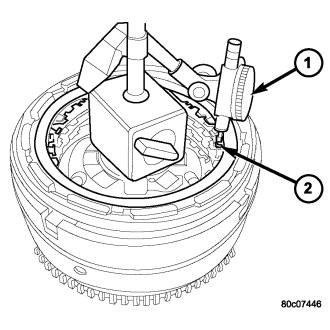
26. Mount a dial indicator to the assembly, push down on the clutch discs, pull up on the reaction plate to ensure the plate is properly seated and zero the indicator against the reverse clutch discs (2) . Apply 20 psi of air pressure to the reverse clutch and record the dial indicator reading. Measure and record Reverse clutch pack measurement in four (4) places, 90° apart. Take average of four measurements and compare with Reverse clutch pack clearance specification. The correct clutch clearance is 0.81-1.24 mm (0.032-0.049 in.). Adjust as necessary. Install the chosen snap-ring and re-measure to verify selection.
| 1 - THRUST BEARING NUMBER 3 | 10 - SNAP-RING (SELECT) |
| 2 - OD HUB/SHAFT | 11 - PLATE |
| 3 - SNAP-RING (WAVE) | 12 - DISC |
| 4 - REV/OD REACTION PLATE | 13 - OD CLUTCH |
| 5 - THRUST BEARING NUMBER 4 | 14 - SNAP-RING (TAPERED) |
| 6 - SNAP-RING (FLAT) | 15 - UD/OD REACTION PLATE |
| 7 - REVERSE HUB/SHAFT | 16 - SNAP-RING (FLAT) |
| 8 - REVERSE CLUTCH | 17 - UD HUB/SHAFT |
| 9 - REVERSE REACTION PLATE | 18 - THRUST BEARING NUMBER 2 |
27. Remove the reverse clutch pack (8) from the input clutch retainer.
28. Install the number 2 thrust bearing (18) onto the underdrive hub (17) with outer race against the hub with petroleum jelly.
29. Install the underdrive hub (17) into the input clutch retainer.
30. Install the number 3 thrust bearing (1) into the overdrive hub (2) with the outer race against the hub with petroleum jelly.
31. Install the overdrive hub (2) into the input clutch retainer.
32. Install the number 4 thrust bearing (5) into the reverse hub with outer race against the hub with petroleum jelly.
33. Install the reverse hub (7) into the input clutch retainer.
34. Install the complete reverse clutch pack (8).
35. Install the reverse reaction plate (9) and snap-ring (10).
36. Push up on reaction plate to allow reverse clutch to move freely.