TRANSMISSION CONTROL MODULE
DESCRIPTION
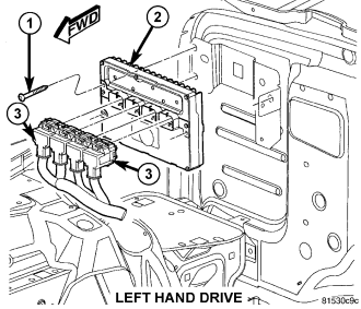
The Transmission Control Module (TCM) is a sub-module within the Powertrain Control Module (PCM) (2).
The PCM (2) is located on the right side of the dash panel in the engine compartment on left hand drive vehicles. The PCM is referred to as the NGC.
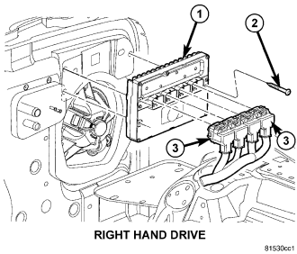
The PCM (1) is located on the left side of the dash panel in the engine compartment on right hand drive vehicles.
OPERATION
The TCM is the controlling unit for all electronic operations of the transmission. The TCM receives information regarding vehicle operation from both direct and indirect inputs, and selects the operational mode of the transmission. Direct inputs are hard-wired to, and used specifically by the TCM. Indirect inputs originate from other components/modules, and are shared with the TCM via the CAN bus.
Some examples of direct inputs to the TCM are:- Battery (B+) voltage
- Ignition “ON” voltage
- Transmission Control Relay (Switched B+)
- Throttle Position Sensor
- Crankshaft Position Sensor (CKP)
- Transmission Range Sensor (TRS)
- Pressure Switches (L/R, 2/4, OD)
- Transmission Temperature Sensor (Integral to TRS)
- Input Shaft Speed Sensor
- Output Shaft Speed Sensor
- Engine/Body Identification
- Manifold Pressure
- Target Idle
- Torque Reduction Confirmation
- Speed Control ON/OFF Switch
- Engine Coolant Temperature
- Ambient/Battery Temperature
- Brake Switch Status
- Scan Tool Communication
Based on the information received from these various inputs, the TCM determines the appropriate shift schedule and shift points, depending on the present operating conditions and driver demand. This is possible through the control of various direct and indirect outputs.
Some examples of TCM direct outputs are:- Transmission Control Relay
- Solenoids (L/R, 2/4, OD and UD)
- Vehicle Speed (to PCM)
- Torque Reduction Request (to PCM)
- Transmission Temperature (to PCM)
- PRNDL Position (to BCM)
In addition to monitoring inputs and controlling outputs, the TCM has other important responsibilities and functions:
- Storing and maintaining Clutch Volume Indices (CVI)
- Storing and selecting appropriate Shift Schedules
- System self-diagnostics
- Diagnostic capabilities (with scan tool)
NOTE: If the TCM has been replaced, the “Quick Learn Procedure” must be performed. (Refer to 8 - ELECTRICAL/ELECTRONIC CONTROL MODULES/TRANSMISSION CONTROL MODULE - STANDARD PROCEDURE)
CLUTCH VOLUME INDEX (CVI)
An important function of the TCM is to monitor Clutch Volume Index (CVI). CVIs represent the volume of fluid needed to compress a clutch pack.
The TCM monitors gear ratio changes by monitoring the Input and Output Speed Sensors. The Input, or Turbine Speed Sensor sends an electrical signal to the TCM that represents input shaft rpm. The Output Speed Sensor provides the TCM with output shaft speed information.
By comparing the two inputs, the TCM can determine transmission gear position. This is important to the CVI calculation because the TCM determines CVIs by monitoring how long it takes for a gear change to occur .
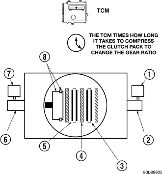
Gear ratios can be determined by using the Scan Tool and reading the Input/Output Speed Sensor values in the “Monitors” display. Gear ratio can be obtained by dividing the Input Speed Sensor value by the Output Speed Sensor value.
For example, if the input shaft is rotating at 1000 rpm and the output shaft is rotating at 500 rpm, then the TCM can determine that the gear ratio is 2:1. In direct drive (3rd gear), the gear ratio changes to 1:1. The gear ratio changes as clutches are applied and released. By monitoring the length of time it takes for the gear ratio to change following a shift request, the TCM can determine the volume of fluid used to apply or release a friction element.
The volume of transmission fluid needed to apply the friction elements are continuously updated for adaptive controls. As friction material wears, the volume of fluid need to apply the element increases.
Certain mechanical problems within the input clutch assembly (broken return springs, out of position snap rings, excessive clutch pack clearance, improper assembly, etc.) can cause inadequate or out-of-range element volumes. Also, defective Input/Output Speed Sensors and wiring can cause these conditions. The following chart identifies the appropriate clutch volumes and when they are monitored/updated:
| CLUTCH VOLUMES | ||||||
| Clutch | When Updated | Proper Clutch Volume | ||||
| Shift Sequence | Oil Temperature | Throttle Angle | ||||
| L/R | 2-1 or 3-1 coast downshift | > 21° C (70° F) | < 5° | 35 to 83 | ||
| 2/4 | 1-2 shift | > 43° C (110° F) | 5 - 54° | 20 to 77 | ||
| OD | 2-3 shift | 48 to 150 | ||||
| UD | 4-3 or 4-2 shift | > 5° | 24 to 70 | |||
SHIFT SCHEDULES
As mentioned earlier, the TCM has programming that allows it to select a variety of shift schedules. Shift schedule selection is dependent on the following:
- Shift lever position
- Throttle position
- Engine load
- Fluid temperature
- Software level
As driving conditions change, the TCM appropriately adjusts the shift schedule. Refer to the following table 42RLE Shift Schedule to determine the appropriate operation expected, depending on driving conditions.
| Schedule | Condition | Expected Operation |
| Extreme Cold | Oil temperature at start-up below -27° C (-16° F) | Park, Reverse, Neutral and 2nd gear only (prevents shifting which may fail a clutch with frequent shifts) |
| Cold | Oil temperature at start-up above -25° C (-12° F) and below 2° C (36° F) | - Delayed 2-3 upshift (approximately 22-31 mph) |
| - Delayed 3-4 upshift (45-53 mph) | ||
| - Early 4-3 costdown shift (approximately 30 mph) | ||
| - Early 3-2 coastdown shift (approximately 17 mph) | ||
| - High speed 4-2, 3-2, 2-1 kickdown shifts are prevented | ||
| - No EMCC | ||
| Warm | Oil temperature at start-up above 2° C (36° F) and below 27° C (80° F) | - Normal operation (upshift, kickdowns, and coastdowns) |
| - No EMCC | ||
| Hot | Oil temperature at start-up above 27° C (80° F) | - Normal operation (upshift, kickdowns, and coastdowns) |
| - Full EMCC, no PEMCC except to engage FEMCC (except at closed throttle at speeds above 70-83 mph) | ||
| Overheat | Oil temperature above 115° C (240° F) or engine coolant temperature above 118° C (244° F) | - Delayed 2-3 upshift (25-32 mph) |
| - Delayed 3-4 upshift (41-48 mph) | ||
| - 3rd gear FEMCC from 30-48 mph | ||
| - 3rd gear PEMCC from 27-31 mph | ||
| Super Overheat | Oil temperature above 127° C (260° F) | - All "Overheat" shift schedule features apply |
| - 2nd gear PEMCC above 22 mph | ||
| - Above 22 mph the torque converter will not unlock unless the throttle is closed or if a wide open throttle 2nd PEMCC to 1 kickdown is made |
STANDARD PROCEDURE - TCM QUICK LEARN
The quick learn procedure requires the use of the scan tool.
This program allows the electronic transmission system to recalibrate itself. This will provide the proper transmission operation. The quick learn procedure should be performed if any of the following procedures are performed:
- Transmission Assembly Replacement
- Transmission Control Module Replacement
- Solenoid Pack Replacement
- Clutch Plate and/or Seal Replacement
- Valve Body Replacement or Recondition
To perform the Quick Learn Procedure, the following conditions must be met:
- The brakes must be applied
- The engine speed must be above 500 rpm
- The throttle angle (TPS) must be less than 3 degrees
- The shift lever position must stay in PARK until prompted to shift to overdrive
- The shift lever position must stay in overdrive after the Shift to Overdrive prompt until the scan tool indicates the procedure is complete.
- The calculated oil temperature must be above 60°F (16°C) and below 200°F (93°C)