AUTOMATIC TRANSMISSION - 545RFE
- DESCRIPTION
- OPERATION
- STANDARD PROCEDURE - ALUMINUM THREAD REPAIR
- REMOVAL
- DISASSEMBLY
- CLEANING
- INSPECTION
- ASSEMBLY
- INSTALLATION
DESCRIPTION
The 545RFE automatic transmission is a sophisticated, multi-range, electronically controlled transmission which combines optimized gear ratios for responsive performance, state of the art efficiency features and low NVH. Other features include driver adaptive shifting and three planetary gear sets to provide wide ratio capability with precise ratio steps for optimum driveability. The three planetary gear sets also make available a unique alternate second gear ratio. The primary 2nd gear ratio fits between 1st and 3rd gears for normal through-gear accelerations. The alternate second gear ratio (2prime) allows smoother 4-2 kickdowns at high speeds to provide 2nd gear passing performance over a wider highway cruising range. An additional overdrive ratio (0.67:1) is also provided for greater fuel economy and less NVH at highway speeds.
The hydraulic portion of the transmission consists of the transmission fluid, fluid passages, hydraulic valves, and various line pressure control components.
The primary mechanical components of the transmission consist of the following:
- Three multiple disc input clutches
- Three multiple disc holding clutches
- Five hydraulic accumulators
- Three planetary gear sets
- Dual Stage Hydraulic oil pump
- Valve body
- Solenoid pack
The Transmission Control Module (TCM) is the “heart” or “brain” of the electronic control system and relies on information from various direct and indirect inputs (sensors, switches, etc.) to determine driver demand and vehicle operating conditions. Depending on the vehicle configuration, the TCM may be a standalone module or it it may be housed along with the Powertrain Control Module (PCM) in a single module. With this information, the TCM can calculate and perform timely and quality shifts through various output or control devices (solenoid pack, transmission control relay, etc.).
TRANSMISSION IDENTIFICATION
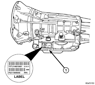
Transmission identification numbers (1) are stamped on the left side of the case just above the oil pan sealing surface . Refer to this information when ordering replacement parts. A label is attached to the transmission case above the stamped numbers. The label gives additional information which may also be necessary for identification purposes.
GEAR RATIOS
The 545RFE gear ratios are:OPERATION
The 545RFE offers full electronic control of all automatic up and downshifts, and features real-time adaptive closed-loop shift and pressure control. Electronic shift and torque converter clutch controls help protect the transmission from damage due to high temperatures, which can occur under severe operating conditions. By altering shift schedules, line pressure, and converter clutch control, these controls reduce heat generation and increase transmission cooling.
To help reduce efficiency-robbing parasitic losses, the transmissions includes a dual-stage transmission fluid pump with electronic output pressure control. Under most driving conditions, pump output capacity greatly exceeds that which is needed to keep the clutches applied. The 45RFE/545RFE pump-pressure control system monitors input torque and adjusts the pump pressure accordingly. The primary stage of the pump works continuously; the second stage is bypassed when demand is low. The control system also monitors input and output speed and, if incipient clutch slip is observed, the pressure control solenoid duty cycle is varied, increasing pressure in proportion to demand.
A high-travel torque converter damper assembly allows earlier torque converter clutch engagement to reduce slippage. Needle-type thrust bearings reduce internal friction. The 45RFE/545RFE is packaged in a one-piece die-cast aluminum case. To reduce NVH, the case has high lateral, vertical and torsional stiffness. It is also designed to maximize the benefit of the structural dust cover that connects the bottom of the bell housing to the engine bedplate, enhancing overall power train stiffness. Dual filters protect the pump and other components. A cooler return filter is added to the customary main sump filter. Independent lubrication and cooler circuits assure ample pressure for normal transmission operation even if the cooler is obstructed or the fluid cannot flow due to extremely low temperatures.
The hydraulic control system design (without electronic assist) provides the transmission with PARK, REVERSE, NEUTRAL, SECOND, and THIRD gears, based solely on driver shift lever selection. This design allows the vehicle to be driven (in “limp-in” mode) in the event of a electronic control system failure, or a situation that the Transmission Control Module (TCM) recognizes as potentially damaging to the transmission.
The TCM also performs certain self-diagnostic functions and provides comprehensive information (sensor data, DTC's, etc.) which is helpful in proper diagnosis and repair. This information can be viewed with the scan tool.
STANDARD PROCEDURE - ALUMINUM THREAD REPAIR
Damaged or worn threads in the aluminum transmission case and valve body can be repaired by the use of Heli-Coils™, or equivalent. This repair consists of drilling out the worn-out damaged threads. Then tap the hole with a special Heli-Coil™ tap, or equivalent, and installing a Heli-Coil™ insert, or equivalent, into the hole. This brings the hole back to its original thread size.
Heli-Coil™, or equivalent, tools and inserts are readily available from most automotive parts suppliers.
REMOVAL
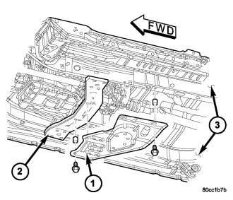
1. Disconnect the negative battery cable.
2. Raise and support the vehicle
3. Remove any necessary skid plates (1). (Refer to 13 - FRAMES & BUMPERS/FRAME/TRANSFER CASE SKID PLATE - REMOVAL)
4. Mark propeller shaft and axle companion flanges for assembly alignment.
5. Remove the rear propeller shaft. (Refer to 3 - DIFFERENTIAL & DRIVELINE/PROPELLER SHAFT/PROPELLER SHAFT - REMOVAL)
6. Remove the front propeller shaft, if necessary. (Refer to 3 - DIFFERENTIAL & DRIVELINE/PROPELLER SHAFT/PROPELLER SHAFT - REMOVAL)
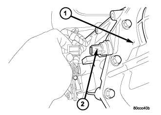
7. Disengage the output speed sensor connector from the output speed sensor (2).
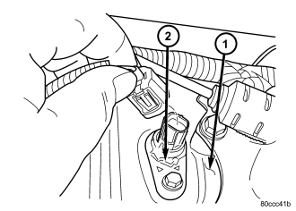
8. Disengage the input speed sensor connector from the input speed sensor (2).
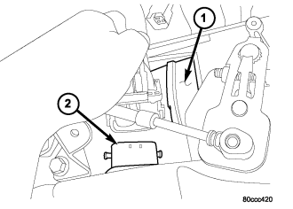
9. Disengage the transmission solenoid/TRS assembly connector from the transmission solenoid/TRS assembly (2).
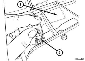
10. Disengage the line pressure sensor connector from the line pressure sensor (2).
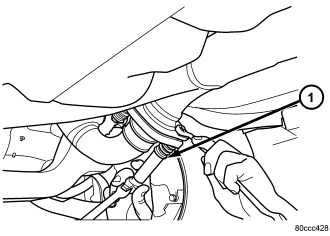
11. Remove the bolts (1) holding the exhaust crossover pipe to the pre-catalytic converter pipe flanges.
12. Remove the bolts holding the exhaust crossover pipe to the catalytic converter flange.
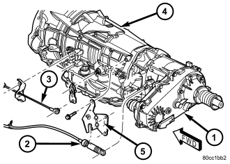
13. Disconnect gearshift cable (2) from transmission manual valve lever.
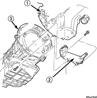
14. Disengage the shift cable from the cable support bracket.
15. Remove the starter motor.
16. Remove the engine to transmission collar (2).
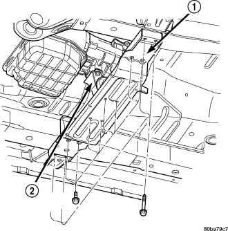
17. Rotate crankshaft in clockwise direction until converter bolts are accessible. Then remove bolts one at a time. Rotate crankshaft with socket wrench on dampener bolt.
18. Disconnect transmission fluid cooler lines at transmission fittings and clips.
19. Disconnect the transmission vent hose from the transmission.
20. Remove transfer case.
21. Support rear of engine with safety stand or jack.
22. Raise transmission slightly with service jack to relieve load on crossmember and supports.
23. Remove bolts securing rear support and cushion (2) to transmission and crossmember (1).
24. Remove bolts attaching crossmember to frame and remove crossmember.
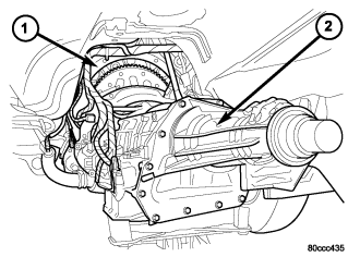
25. Remove all remaining converter housing bolts.
26. Disconnect fuel line retainers at the transmission (if necessary).
27. Carefully work transmission and torque converter assembly rearward off engine block dowels.
28. Hold torque converter in place during transmission removal.
29. Lower transmission and remove assembly (2) from under the vehicle.
30. To remove torque converter, carefully slide torque converter out of the transmission.
DISASSEMBLY
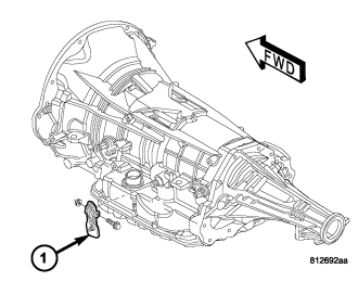
1. Drain fluid from transmission.
2. Clean exterior of transmission with suitable solvent or pressure washer.
3. Remove the torque converter from the transmission.
4. Remove the manual shift lever (1) from the transmission.
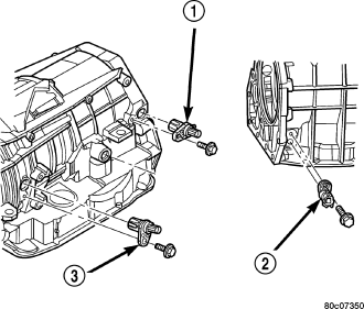
5. Remove the input (3), output (1), and line pressure sensors (2) from the transmission case.
6. Inspect the ends of the sensors for debris, which may indicate the nature of the transmission failure.
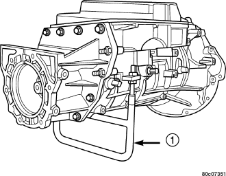
7. Install Support Stand 8257 (1) onto the transmission case.
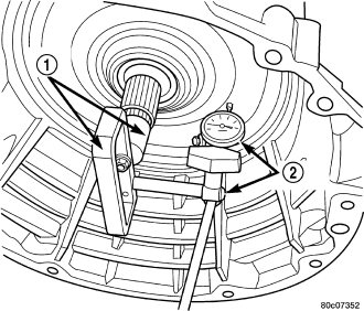
8. Using Adapter 8266-1 from End-Play Tool Set 8266 (1) and Dial Indicator C-3339 (2), measure and record the input shaft end-play.
NOTE: When measuring the input shaft end-play, two "stops" will be felt. When the input shaft is pushed inward and the dial indicator zeroed, the first "stop" felt when the input shaft is pulled outward is the movement of the input shaft in the input clutch housing hub. This value should not be included in the end-play measured value and therefore must be recorded and subtracted from the dial indicator reading.
9. Remove the bolts holding the transmission extension/adapter housing to the transmission case.
10. Remove the extension/adapter housing from the transmission case.
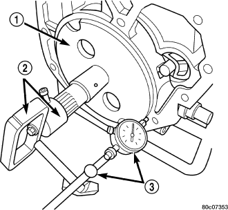
11. Using Alignment Plate 8261 (1), Adapter 8266-17 from End-Play Tool Set 8266 (2) and Dial Indicator C-3339 (3), measure and record the output shaft end-play.
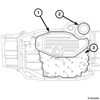
12. Remove the bolts holding the transmission oil pan to the transmission case.
13. Remove the transmission oil pan from the transmission case.
14. Remove the primary oil filter (1) and the oil cooler return filter (2).
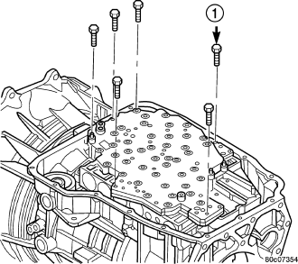
15. Remove the bolts (1) holding the valve body to the transmission case.
16. Remove the valve body from the transmission case.
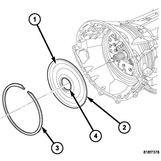
17. Remove the outer snap-ring (3) securing the transmission front cover (1) into the transmission case.
18. Reaching through a case opening in the valve body area with a long blunted tool, remove the transmission front cover (1) from the transmission case.
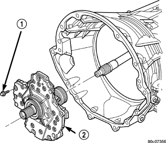
19. Remove the bolts (1) holding the oil pump into the transmission case.
20. Remove the oil pump (2). Hold inward on the input shaft to prevent pulling the input clutch assembly with the oil pump.
CAUTION: If the input shaft is not held during oil pump removal, the input clutch assembly will attempt to move forward with the oil pump and the numbers 2, 3, or 4 bearings inside the input clutch assembly may become dislodged.
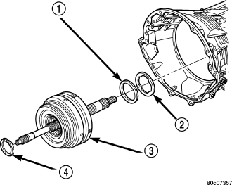
21. Remove the number 1 thrust bearing (4) from the input clutch assembly.
22. Remove the input clutch assembly (3) from the transmission case.
23. Remove the number 5 thrust bearing (1) and selective thrust plate (2) from the input clutch assembly (3) , or the 4C clutch retainer/bulkhead.
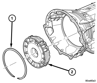
24. Remove the 4C clutch retainer/bulkhead tapered snap-ring (1) from the transmission case.
25. Remove the 4C clutch retainer/bulkhead (2) from the transmission case.
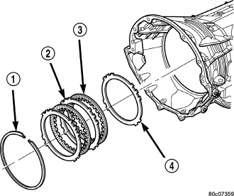
26. Remove the front 2C clutch pack snap-ring (1) from the transmission case.
27. Remove the 2C clutch pack (2, 3, 4) from the transmission case.
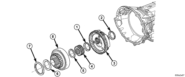
| Remove Reaction Annulus and Carrier |
| 1 - THRUST BEARING NUMBER 8 | 5 - THRUST BEARING NUMBER 7 |
| 2 - THRUST BEARING NUMBER 9 | 6 - THRUST PLATE (SELECT) |
| 3 - REACTION PLANETARY CARRIER | 7 - THRUST BEARING NUMBER 6 |
| 4 - REACTION SUN GEAR | 8 - REACTION ANNULUS |
28. Remove the rear selective thrust plate (6) and number 6 thrust bearing (7) from the reaction annulus (8).
29. Remove the reaction annulus (8) from the reaction planetary carrier (3).
30. Remove the number 7 thrust bearing (5).
31. Remove the reaction sun gear (4).
32. Remove the number 8 thrust bearing (1) from the reaction planetary carrier (3).
33. Remove the reaction planetary carrier (3) . Note that this planetary gear set has three pinion gears.
34. Remove the number 9 thrust bearing (2) from the reverse planetary gear set.
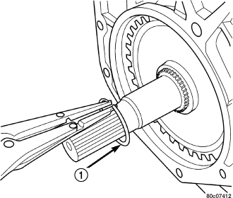
35. Remove the snap-ring (1) holding the park sprag gear onto the output shaft.
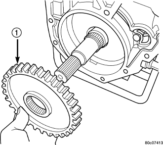
36. Remove the park sprag gear (1) from the output shaft.
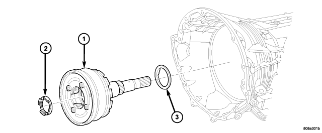
37. Remove the input/reverse planetary assembly (1).
38. Remove the number 12 thrust bearing (3) from the input/reverse planetary assembly (1).
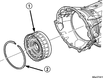
39. Remove the snap-ring (2) holding the low/reverse clutch retainer (1) into the transmission case.
40. Remove the low/reverse clutch retainer (1) from the transmission case.
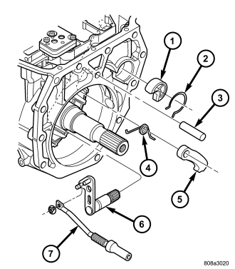
41. Remove the park rod (7) and e-clip.
42. Remove the park rod guide snap-ring (2).
43. Remove the park rod guide (1).
44. Remove the park pawl pivot shaft (3), park pawl (5), and spring (4).
45. Remove the manual selector shaft (6).
46. Remove the manual selector shaft seal.
47. Remove the dipstick tube seal.
CLEANING
The use of crocus cloth is permissible where necessary, providing it is used carefully. When used on shafts, or valves, use extreme care to avoid rounding off sharp edges. Sharp edges are vital as they prevent foreign matter from getting between the valve and valve bore.
Do not reuse oil seals, gaskets, seal rings, or O-rings during overhaul. Replace these parts as a matter of course. Also do not reuse snap rings or E-clips that are bent or distorted. Replace these parts as well.
Lubricate transmission parts with Mopar® ATF +4, Automatic Transmission Fluid, during overhaul and assembly. Use petroleum jelly, Mopar® Door Ease, or Ru-Glyde to prelubricate seals, O-rings, and thrust washers. Petroleum jelly can also be used to hold parts in place during reassembly.
Clean the case in a solvent tank. Flush the case bores and fluid passages thoroughly with solvent. Dry the case and all fluid passages with compressed air. Be sure all solvent is removed from the case and that all fluid passages are clear.
NOTE: Do not use shop towels or rags to dry the case (or any other transmission component) unless they are made from lint-free materials. Lint will stick to case surfaces and transmission components and circulate throughout the transmission after assembly. A sufficient quantity of lint can block fluid passages and interfere with valve body operation.
INSPECTION
Inspect the case for cracks, porous spots, worn bores, or damaged threads. Damaged threads can be repaired with Helicoil® thread inserts. However, the case will have to be replaced if it exhibits any type of damage or wear.
ASSEMBLY
NOTE: Apply trans jell or petroleum jelly to all slide portions, rolling contacts surfaces, thrust surfaces etc. to prevent burnout during initial operation. Lubricate O-rings and O-ring seals with MOPAR® ATF+4. Soak all friction disks in MOPAR® ATF+4 for at least two hours before assembly of clutch packs.
NOTE: Clean and inspect all components. Replace any components which show evidence of excessive wear or scoring.
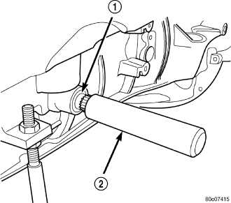
1. Install a new selector shaft seal (1) using Seal Installer 8253 (2).
2. Install the manual selector shaft and retaining screw. Tighten the manual selector shaft retaining screw to 28 N·m (250 in.lbs.).
3. Install the manual shift lever (1) onto the manual selector shaft. Tighten the retaining cross-bolt to 16 N·m (140 in.lbs.).
4. Install the park pawl (5), spring (4), and shaft (3).
5. Install the park rod (7) and e-clip.
6. Install the park rod guide (1) and snap-ring (2).
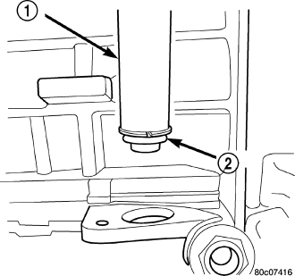
7. Install a new fill tube seal (2) using Seal Installer 8254 (1).
NOTE: Before final assembly of transmission centerline, the 2C/4C clutch components should be installed into position and measured as follows:
8. Install the 2C reaction plate (4) with the beveled edge down (rearward) into the transmission case.
9. Install the 2C clutch pack (2, 3) into the transmission case.
10. Install the flat 2C clutch snap-ring (1) into the transmission case.
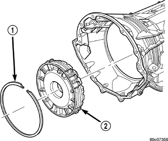
11. Install the 4C retainer/bulkhead (2) into the transmission case. Make sure that the oil feed holes are pointing toward the valve body area.
12. Install the 4C retainer/bulkhead tapered snap-ring (1) into the transmission case. Make sure that the open ends of the snap-ring are located in the case opening toward the valve body area.
13. Using a feeler gauge through the opening in the rear of the transmission case, measure the 2C clutch pack clearance between the 2C reaction plate and the transmission case at four different points. The average of these measurements is the 2C clutch pack clearance. The correct clutch clearance is 0.455-1.335 mm (0.018-0.053 in.). The reaction plate is not selective. If the clutch pack clearance is not within specification, the reaction plate, all the friction discs, and steels must be replaced.
14. Remove the 4C retainer/bulkhead and all of the 2C clutch components from the transmission case.
15. Install the low/reverse clutch assembly (1). Make sure that the oil feed hole points toward the valve body area and that the bleed orifice is aligned with the notch in the rear of the transmission case.
16. Install the snap-ring (2) to hold the low/reverse clutch retainer into the transmission case. The snap-ring is tapered and must be installed with the tapered side forward. Once installed, verify that the snap-ring is fully seated in the snap-ring groove.
17. Air check the low/reverse clutch and verify correct overrunning clutch operation.
18. Install the number 12 thrust bearing (3) over the output shaft and against the rear planetary gear set. The flat side of the bearing goes toward the planetary gearset and the raised tabs on the inner race should face the rear of the transmission.
19. Install the reverse/input planetary assembly (1) through the low/reverse clutch assembly.
20. Install the park sprag gear (1) onto the output shaft.
21. Install the snap-ring (1) to hold the park sprag onto the output shaft.
22. Install the 2C reaction plate (4) with the beveled edge down (rearward) into the transmission case.
23. Install the 2C clutch pack (2, 3, 4) into the transmission case.
| Install Reaction Annulus and Carrier |
| 1 - THRUST BEARING NUMBER 8 | 5 - THRUST BEARING NUMBER 7 |
| 2 - THRUST BEARING NUMBER 9 | 6 - THRUST PLATE (SELECT) |
| 3 - REACTION PLANETARY CARRIER | 7 - THRUST BEARING NUMBER 6 |
| 4 - REACTION SUN GEAR | 8 - REACTION ANNULUS |
24. Install the number 8 thrust bearing (1) inside the reaction carrier with the outer race against the reaction planetary carrier (3).
25. Install the reaction planetary gear set and the number 9 thrust bearing (2), with the inner race against the reaction planetary carrier (3), into the transmission case.
26. Install the flat 2C clutch snap-ring into the transmission case.
27. Install the reaction sun gear (4) into the reaction planetary gear set. Make sure the small shoulder is facing the front of the transmission.
28. Install the number 7 thrust bearing (5) onto the reaction sun gear (4) with the inner race against the sun gear.
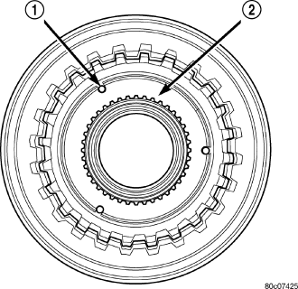
29. Install the output shaft selective thrust plate (2) onto the reaction annulus with the oil grooves facing the annulus gear and the lugs (1) and notches aligned as shown.
| Install Reaction Annulus and Carrier |
| 1 - THRUST BEARING NUMBER 8 | 5 - THRUST BEARING NUMBER 7 |
| 2 - THRUST BEARING NUMBER 9 | 6 - THRUST PLATE (SELECT) |
| 3 - REACTION PLANETARY CARRIER | 7 - THRUST BEARING NUMBER 6 |
| 4 - REACTION SUN GEAR | 8 - REACTION ANNULUS |
30. Install the number 6 thrust bearing (7) against the output shaft selective thrust plate (6) with the flat side against the thrust plate and the raised tabs on the inner race facing the front of the transmission.
31. Install the reaction annulus (8) into the reaction planetary gear set.
32. Install the 4C retainer/bulkhead (2) into the transmission case. Make sure that the oil feed holes are pointing toward the valve body area. Rotate the reaction annulus during the installation of the 4C retainer/bulkhead to ease installation.
33. Install the 4C retainer/bulkhead tapered snap-ring (1) into the transmission case with the taper toward the front of the case. Make sure that the open ends of the snap-ring are located in the case opening toward the valve body area.
34. Air check the 2C and 4C clutch operation.
35. Using Alignment Plate 8261 (1), Adapter 8266-17 from End-Play Tool Set 8266 (2) and Dial Indicator C-3339 (3), measure and record the output shaft end-play. The correct output shaft end-play is 0.22-0.55 mm (0.009-0.021 in.). Adjust as necessary. Install the chosen output shaft selective thrust plate and re-measure end-play to verify selection.
36. Apply a bead of RTV silicone and install the extension/adapter housing onto the transmission case.
37. Install and torque the bolts to hold the extension/adapter housing onto the transmission case. The correct torque is 54 N·m (40 ft.lbs.).
38. Install the number 5 thrust bearing (1) and selective thrust plate (2) onto the 4C retainer/bulkhead. Be sure that the outer race of the bearing is against the thrust plate.
39. Install the input clutch assembly (3) into the transmission case. Make sure that the input clutch assembly is fully installed by performing a visual inspection through the input speed sensor hole. If the tone wheel teeth on the input clutch assembly are centered in the hole, the assembly is fully installed.
40. Install the number 1 thrust bearing (4) with the outer race up in the pocket of the input clutch assembly.
41. Install the oil pump (2) into the transmission case making certain the oil pump is flush with the transmission case.
42. Install the bolts (1) to hold the oil pump into the transmission case. Tighten the oil pump bolts to 28 N·m (250 in.lbs.).
NOTE: If NO input shaft end play is noted, disassemble the input clutch assembly and check for the #2, #3, or #4 thrust bearing fallen out of position or cracked. Replace any cracked thrust bearing and reassemble using trans jell or petroleum jelly to retain the thrust bearings.
43. Using Adapter 8266-1 from End-Play Tool Set 8266 (1) and Dial Indicator C-3339 (2), measure and record the input shaft end-play. The correct end-play is 0.46-0.89 mm (0.018-0.035 in.). Adjust as necessary. Install the chosen thrust plate on the number 5 thrust bearing and re-measure end-play to verify selection.
NOTE: When measuring the input shaft end-play, two "stops" will be felt. When the input shaft is pushed inward and the dial indicator zeroed, the first "stop" felt when the input shaft is pulled outward is the movement of the input shaft in the input clutch housing hub. This value should not be included in the end-play measured value and therefore must be recorded and subtracted from the dial indicator reading.
NOTE: To avoid contamination and garter spring dislodgement, do not handle the front cover seal when installing the front cover into the transmission case.
44. Position the new front cover (1) onto transmission case.
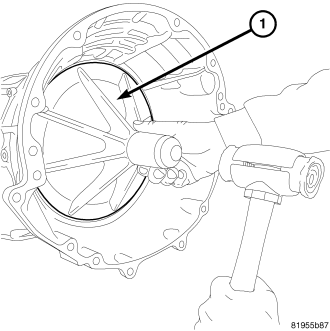
45. Using a dead-blow mallet and the Front Cover installation tool 9955, install the front cover into the transmission case .
46. Install the snap ring into the transmission case.
47. Install the valve body. Verify that the pin on the manual lever has properly engaged the TRS selector plate. Tighten the valve body to transmission case bolts (1) to 12 N·m (105 in.lbs.).
CAUTION: The primary oil filter seal MUST be fully installed flush against the oil pump body. DO NOT install the seal onto the filter neck and attempt to install the filter and seal as an assembly. Damage to the transmission will result.
48. Install a new primary oil filter seal in the oil pump inlet bore. Seat the seal in the bore with the butt end of a hammer, or other suitable tool.
49. Install the primary oil filter (1) and the oil cooler return filter (2) . Tighten the screw to hold the primary oil filter to the valve body to 4.5 N·m (40 in.lbs.). Using Filter Wrench 8321, tighten the cooler return oil filter to the transmission case to 9.5 N·m (84 in.lbs.).
50. Apply RTV silicone to the oil pan and install the transmission oil pan. Tighten the bolts to 12 N·m (105 in.lbs.).
51. Install the input (3), output (1), and line pressure sensors (2). Tighten the bolts to 12 N·m (105 in.lbs.).
INSTALLATION
1. Check torque converter hub and hub drive flats for sharp edges burrs, scratches, or nicks. Polish the hub and flats with 320/400 grit paper and crocus cloth if necessary. Verify that the converter hub o-ring is properly installed and is free of any debris. The hub must be smooth to avoid damaging pump seal at installation.
2. If a replacement transmission is being installed, transfer any components necessary, such as the manual shift lever and shift cable bracket, from the original transmission onto the replacement transmission.
3. Lubricate oil pump seal lip with transmission fluid.
4. Align converter and oil pump.
5. Carefully insert converter in oil pump. Then rotate converter back and forth until fully seated in pump gears.
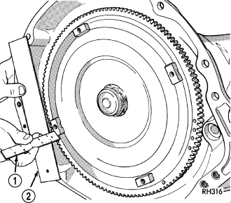
6. Check converter seating with steel scale (1) and straightedge (2). Surface of converter lugs should be at least 13 mm (1/2 in.) to rear of straightedge when converter is fully seated.
7. Temporarily secure converter with C-clamp.
8. Position transmission on jack and secure it with chains.
9. Check condition of converter driveplate. Replace the plate if cracked, distorted or damaged. Also be sure transmission dowel pins are seated in engine block and protrude far enough to hold transmission in alignment.
10. Apply a light coating of Mopar® High Temp Grease to the torque converter hub pocket in the rear pocket of the engine's crankshaft.
11. Raise transmission (2) and align the torque converter with the drive plate and transmission converter housing with the engine block.
12. Move transmission forward. Then raise, lower or tilt transmission to align the converter housing with engine block dowels.
13. Carefully work transmission forward and over engine block dowels until converter hub is seated in crankshaft. Verify that no wires, or the transmission vent hose, have become trapped between the engine block and the transmission.
14. Install two bolts to attach the transmission to the engine.
15. Install remaining torque converter housing to engine bolts. Tighten the four upper bolts to 41 N· ( 30 ft. lbs.), tighten the four lower bolts to 54 N·m (40 ft. lbs.), tighten the four collar bolts to 68 N·m (50 ft.lbs.).
16. Install transfer case, if equipped. Tighten transfer case nuts to 35 N·m (26 ft.lbs.).
17. Install rear transmission crossmember. Tighten crossmember to frame bolts to 68 N·m (50 ft.lbs.).
18. Install rear support to transmission. Tighten bolts to 47 N·m (35 ft.lbs.).
19. Lower transmission onto crossmember and install bolts attaching transmission mount to crossmember. Tighten clevis bracket to crossmember bolts to 47 N·m (35 ft.lbs.). Tighten the clevis bracket to rear support bolt to 68 N·m (50 ft.lbs.).
20. Remove engine support fixture.
21. Connect fuel line retainer at transmission (if necessary).
22. Connect gearshift cable (3) to support bracket and transmission manual lever.
23. Connect wires to solenoid and pressure switch assembly (2).
24. Connect wires to input speed sensor (2).
25. Connect wires to output speed sensor (2).
26. Connect wires to line pressure sensor (2). Be sure transmission harnesses are properly routed.
CAUTION: It is essential that correct length bolts be used to attach the converter to the driveplate. Bolts that are too long will damage the clutch surface inside the converter.
27. Install torque converter-to-driveplate bolts. Tighten bolts to 31 N·m (270 in.lbs.).
28. Install starter motor and cooler line bracket.
29. Connect cooler lines to transmission.
30. Install transmission fill tube.
31. Install exhaust components (1).
32. Install the structural dust cover (2) (Refer to 9 - ENGINE/ENGINE BLOCK/STRUCTURAL COVER - INSTALLATION) onto the transmission and the engine.
33. Align and connect propeller shaft(s).
34. Adjust gearshift cable if necessary.
35. Install any skid plates (1) removed previously. (Refer to 13 - FRAMES & BUMPERS/FRAME/TRANSFER CASE SKID PLATE - INSTALLATION)
36. Lower vehicle.
37. Fill transmission with Mopar® ATF +4, type 9602, Automatic Transmission Fluid.