STANDARD PROCEDURE
VALVE SEALS - IN VEHICLE
1. Disconnect the negative battery cable.
2. Remove the intake manifold/cylinder head cover (Refer to 9 - ENGINE/CYLINDER HEAD/CYLINDER HEAD COVER(S) - REMOVAL).
NOTE: Rocker arms and lifters must be kept in order of removal and stored in the up right position.
3. Position the rocker arms aside. (Refer to 9 - ENGINE/CYLINDER HEAD/ROCKER ARM / ADJUSTER ASSY - REMOVAL).
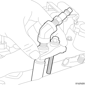
4. Install special tool VM.1072A, compression tester adaptor into the injector hole and retain with an injector hold down (2) bolt .
5. Prepare special tool MD998772A (1) for usage by inverting the tool to cylinder head holding screws so that the thread size matches the cylinder head.
6. Install special tool MD998772A (1) onto cylinder head and using adaptor MD998772A-15 (2), place the adaptor over the valve spring.
7. Connect a regulated air supply (3) to VM.1072A (4), and pressurize the cylinder.
8. Place shop towels around the working area of the cylinder head to prevent valve locks from accidently entering the engine.
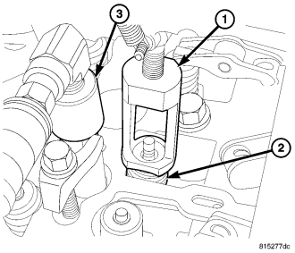
9. Using adaptor MD998772A-15 (1), collapse the valve spring (2) and remove the locks .
10. Remove the valve spring (2) assembly.
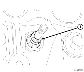
11. Remove the valve seal.
12. Repeat this procedure for all cylinders.
VALVE SERVICE
This procedure is done with the engine cylinder head removed from the block.
DISASSEMBLY
1. Remove the engine cylinder head from the cylinder block (Refer to 9 - ENGINE/CYLINDER HEAD - REMOVAL).
2. Use Valve Spring Compressor Tool and compress each valve spring.
3. Remove the valve locks, retainers, and springs.
4. Use a smooth stone or a jewelers file to remove any burrs on the top of the valve stem, especially around the groove for the locks.
5. Remove the valves, and place them in a rack in the same order as removed.
VALVE CLEANING
1. Clean all carbon deposits from the combustion chambers, valve ports, valve stems, valve stem guides and head.
2. Clean all residue and gasket material from the engine cylinder head machined gasket surface.
INSPECTION
1. Inspect for cracks in the combustion chambers and valve ports.
2. Inspect for cracks on the exhaust seat.
3. Inspect for cracks in the gasket surface at each coolant passage.
4. Inspect valves for burned, cracked or warped heads.
5. Inspect for scuffed or bent valve stems.
6. Replace valves displaying any damage.
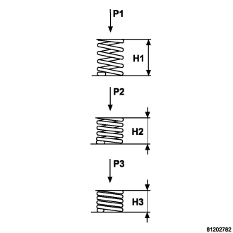
7. Check valve spring height .
VALVE SEAT REFACING
1. Install a pilot of the correct size in the valve guide bore. Reface the valve seat to the specified angle with a good dressing stone. Remove only enough metal to provide a smooth finish.
2. Use tapered stones to obtain the specified seat width when required.
VALVE GUIDES
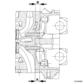
1. Valve Guides height requirement.
2. Measurement A : 16.50 - 17.00 mm. Measurment B : 14.50 - 15.00 mm.
VALVE STEM-TO-GUIDE CLEARANCE MEASUREMENT
1. Measure and record internal diameter of valve guides. Valve guide internal diameter is 6.0 to 6.012 mm (0.2362 to 0.2366 in.).
2. Measure valve stems and record diameters. Intake valve stem diameter 5.952 to 5.97 mm (0.2343 to 0.2350 in). Exhaust valve stem diameter 5.942 to 5.96 mm (0.2339 to 0.2346 in).
3. Subtract diameter of valve stem from internal diameter of its respective valve guide to obtain valve stem clearance in valve guide. Clearance of inlet valve stem in valve guide is 0.03 to 0.06 mm (.0011 to .0023 in). Clearance of exhaust valve stem in valve guide is 0.04 to 0.07 mm (.0015 to .0027 in).
4. If valve stem clearance in valve guide exceeds tolerances, new valve guides must be installed.