CYLINDER HEAD
DESCRIPTION
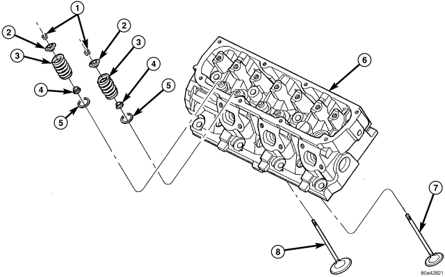
The aluminum cylinder heads are designed to create high flow combustion chambers to improve performance, while minimizing the change to the burn rate in the chamber. The cylinder head incorporates the combustion chamber. Two valves per-cylinder are used with inserted valve seats and guides. A multi-layer steel (MLS) type gasket is used between the cylinder head and engine block.
REMOVAL
1. Drain the cooling system. (Refer to 7 - COOLING - STANDARD PROCEDURE)
2. Disconnect negative cable from battery.
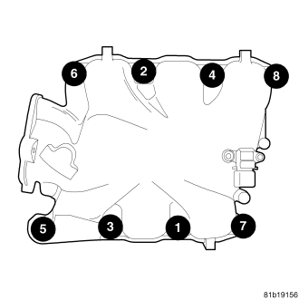
3. Remove upper and lower intake manifolds.
WARNING: INTAKE MANIFOLD GASKET IS MADE OF VERY THIN METAL AND MAY CAUSE PERSONAL INJURY, HANDLE WITH CARE.
4. Remove the cylinder head covers. (Refer to 9 - ENGINE/CYLINDER HEAD/CYLINDER HEAD COVER(S) - REMOVAL)
5. Remove the spark plugs from cylinder head.
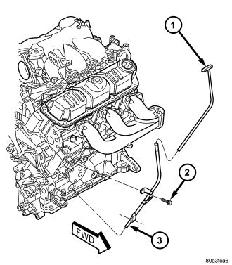
6. Remove the oil level indicator and tube.
7. Remove exhaust manifold(s). (Refer to 9 - ENGINE/MANIFOLDS/EXHAUST MANIFOLD - REMOVAL)
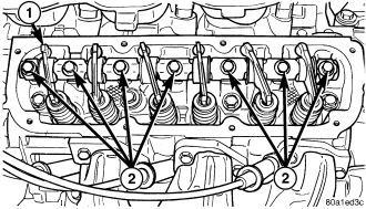
8. Remove rocker arm and shaft assemblies (2). (Refer to 9 - ENGINE/CYLINDER HEAD/ROCKER ARMS - REMOVAL) Remove push rods and mark positions to ensure installation in original locations.
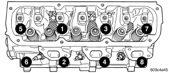
9. Remove the eight head bolts from each cylinder head and remove cylinder heads.
CLEANING
To ensure engine gasket sealing, proper surface preparation must be performed, especially with the use of aluminum engine components and multi-layer steel cylinder head gaskets.
NOTE: Multi-Layer Steel (MLS) head gaskets require a scratch free sealing surface.
Remove all gasket material from cylinder head and block (Refer to 9 - ENGINE - STANDARD PROCEDURE). Be careful not to gouge or scratch the aluminum head sealing surface.
Clean all engine oil passages.
INSPECTION
1. Before cleaning, check for leaks, damage and cracks.
2. Clean cylinder head and oil passages.
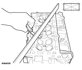
3. Check cylinder head for flatness .
4. Cylinder head must be flat within:
- Standard dimension = less than 0.05 mm (0.002 inch.)
- Service Limit = 0.2 mm (0.008 inch.)
- Grinding Limit = Maximum of 0.2 mm (0.008 inch.) is permitted.
CAUTION: 0.20 mm (0.008 in.) MAX is a combined total dimension of the stock removal limit from cylinder head and block top surface (Deck) together.
INSTALLATION
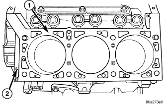
1. Clean all sealing surfaces of engine block and cylinder heads. (Refer to 9 - ENGINE - STANDARD PROCEDURE)
2. Position new gasket(s) on engine block . The left bank gasket is identified with the “L” stamped in the exposed area of the gasket located at front of engine (shown in ). The right bank gasket is identified with a “R” stamped in the exposed area of the gasket also, but is located at the rear of the engine.
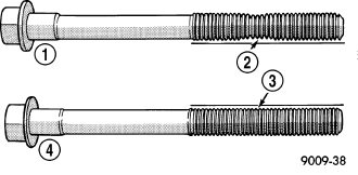
3. The cylinder head bolts are torqued using the torque yield method, they should be examined BEFORE reuse. If the threads are necked down, the bolts must be replaced .
4. Necking can be checked by holding a scale or straight edge against the threads. If all the threads do not contact the scale the bolt should be replaced.
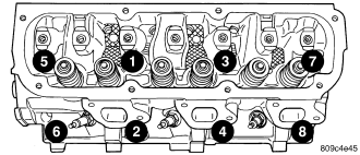
5. Tighten the cylinder head bolts 1–8 in the sequence shown in . Using the 4 step torque turn method, tighten according to the following values:
- Step 1: Bolts 1 – 8 to 61 N·m (45 ft. lbs.)
- Step 2: Bolts 1 – 8 to 88 N·m (65 ft. lbs.)
- Step 3: Bolts 1 – 8 (again) to 88 N·m (65 ft. lbs.)
- Step 4: Bolts 1 – 8 turn an additional 1/4 Turn. (Do not use a torque wrench for this step.)
NOTE: Bolt torque after 1/4 turn should be over 122 N·m (90 ft. lbs.). If not, replace the bolt.
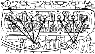
6. Inspect and replace worn or bent push rods.
7. Install the push rods.
8. Install the rocker arm and shaft assemblies (2). (Refer to 9 - ENGINE/CYLINDER HEAD/ROCKER ARMS - INSTALLATION)
9. Install the cylinder head covers. (Refer to 9 - ENGINE/CYLINDER HEAD/CYLINDER HEAD COVER(S) - INSTALLATION).
10. Install the exhaust manifolds. (Refer to 9 - ENGINE/MANIFOLDS/EXHAUST MANIFOLD - INSTALLATION)
11. Install new O-ring on oil level indicator tube. Install oil level indicator tube assembly .
12. Install upper and lower intake manifolds. (Refer to 9 - ENGINE/MANIFOLDS/INTAKE MANIFOLD - INSTALLATION)
13. Fill the cooling system. (Refer to 7 - COOLING - STANDARD PROCEDURE)
14. Connect negative cable to battery.