TRANSFER CASE - NV241OR
- DESCRIPTION
- OPERATION
- DIAGNOSIS AND TESTING - TRANSFER CASE
- REMOVAL
- DISASSEMBLY
- CLEANING
- INSPECTION
- ASSEMBLY
- INSTALLATION
DESCRIPTION
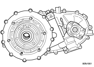
The NV241OR transfer case is a part-time transfer case with a low-range gear system. It provides three operating ranges plus a NEUTRAL position. The low range position provides a gear reduction ratio of 4.0:1 for increased low speed torque capability.
The gear cases, retainer and extension are all of aluminum. Drive sprockets and an interconnecting drive chain are used to transmit engine torque to the front/rear propeller shafts. The mainshaft, input gear and front output shaft are supported by ball and needle bearings.
IDENTIFICATION
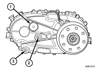
An identification tag (1) is attached to the rear case of every transfer case. The tag provides the transfer case model number, assembly number, serial number, and low range ratio.
The transfer case serial number also represents the date of build.
OPERATION
OPERATING RANGES
Transfer case operating ranges are:
- 2H (2-wheel drive)
- 4H (4-wheel drive)
- 4LO (4-wheel drive low range
The 2H range is for use on any road surface at any time.
The 4H and 4LO ranges are for off road use only. They are not for use on hard surface roads. The only exception being when the road surface is covered by ice and snow.
The low range reduction gear system is operative in 4LO range only. This range is for extra pulling power in off road situations. Low range reduction ratio is 4.0:1.
SHIFT MECHANISM
The transfer case is operated by an adjustable floor mounted shift linkage. The transfer case shift lever is directly attached to the shift sector. The sector operates the range and mode forks within the transfer case.
A straight line shift pattern is used with a NEUTRAL detent. Lever range positions are imprinted in the shift knob.
SHIFTING
The vehicle must have the transmission placed in NEUTRAL, or the clutch depressed in the case of a manual transmission, and be moving less than 2-3 MPH when shifting into the 4L operating range.
DIAGNOSIS AND TESTING - TRANSFER CASE
Before beginning repair on a suspected transfer case malfunction, check all other driveline components beforehand.
The actual cause of a problem may be related to such items as: front hubs, axles, propeller shafts, wheels and tires, transmission, or clutch instead. If all other driveline components are in good condition and operating properly, refer to the Diagnosis Chart for further information.
| Condition |
Possible Cause |
Correction |
| Transfer Case difficult to shift
or will not shift into desired range. |
1) Vehicle speed too great to permit shifting. |
1) Stop vehicle and shift into desired range. Or, reduce speed to below 3-4 km/h (2-3 mph) before attempting the shift. |
| 2) If vehicle was operated for an extended period in 4H on a dry paved surface, the driveline torque load may be causing a bind. |
2) Stop vehicle and shift the transmission into neutral. Shift the transfer case to 2H and operate vehicle in 2H on dry paved surfaces. |
|
| 3) Transfer case external shift linkage binding. |
3) Lubricate, repair, or replace linkage bushings, or tighten loose components as necessary. |
|
| 4) Insufficient
or incorrect lubricant. |
4) Drain and refill to edge of fill hole with Mopar® ATF +4, type 9602, Automatic Transmission fluid. |
|
| 5) Internal components binding, worn, or damaged. |
5) Disassemble the transfer case and replace worn or damaged components as necessary. |
|
| Transfer Case noisy in all operating ranges. |
1) Insufficient or incorrect lubricant. |
1) Drain and refill to edge of fill hole with Mopar® ATF +4, type 9602, Automatic Transmission fluid. |
| Noisy in, or jumps out of, four wheel drive low range. |
1) Transfer case
not completely engaged in 4L position. |
1) With the transmission in NEUTRAL, or the clutch depressed in the case of a manual transmission and the vehicle moving under 3-4 km/h (2-3 mph), shift the transfer case to NEUTRAL and then shift into the 4L position. |
| 2) Shift linkage out of adjustment. |
2) Adjust linkage. |
|
| 3) Shift linkage loose or binding. |
3) Tighten, lubricate, or repair linkage as necessary. |
|
| 4) Range fork damaged, inserts worn, or fork is binding on the shift rail. |
4) Disassemble unit and repair as necessary. |
|
| 5) Low range gear worn or damaged. |
5) Disassemble unit and repair as necessary. |
|
| Lubricant leaking from output shaft seal or vent. |
1) Transfer case overfilled. |
1) Drain lubricant to the correct level. |
| 2) Vent closed or restricted. |
2) Clear or replace vent as necessary. |
|
| 3) Output shaft seals damaged or installed incorrectly. |
3) Replace seal as necessary. Check to ensure that another component, the propeller shaft slip yoke for example, is not causing damage to seal. |
|
| Abnormal tire wear. |
1) Extended operation on hard, dry surfaces in the 4H position. |
1) Operate vehicle in the 2H position on hard, dry surfaces. |
REMOVAL
1. Raise and support vehicle.
2. Remove skid plate, if equipped. (Refer to 13 - FRAMES & BUMPERS/FRAME/TRANSFER CASE SKID PLATE - REMOVAL)
3. Position drain oil container under transfer case.
4. Remove transfer case drain plug and drain lubricant into container.
5. Disconnect vent hose and vacuum harness at transfer case switch.
6. Disconnect shift rod from grommet in transfer case shift lever, or from floor shift arm whichever provides easy access. Use channel lock style pliers to press rod out of lever grommet.
7. Support transmission with jack stand.
8. Remove rear crossmember.
9. Mark front and rear propeller shafts for assembly reference.
10. Remove front and rear propeller shafts. (Refer to 3 - DIFFERENTIAL & DRIVELINE/PROPELLER SHAFT/PROPELLER SHAFT - REMOVAL)
11. Support transfer case with suitable jack. Secure transfer case to jack with safety chains.
12. Remove nuts attaching transfer case to transmission.
13. Move transfer case assembly rearward until free of transmission output shaft.
14. Lower jack and move transfer case from under vehicle.
DISASSEMBLY
Position transfer case in a shallow drain pan. Remove drain plug and drain any remaining lubricant remaining in case.
REAR EXTENSION, RETAINER, AND REAR CASE
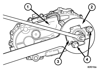
1. Install bolts (4) into two threaded holes in the rear propeller shaft companion flange 180° apart.
2. Place the Holder 6719 (2) over the two bolts and use the Holder to remove the rear companion flange nut.
3. Remove the rear companion flange (3) from the output shaft.
NOTE: The companion flange is a taper fit onto the output shaft. It may be necessary to use Puller 8992 to remove the companion flange.
4. There is a seal slinger located on the rear of the companion flange that can be replaced if necessary. Use a suitable cold chisel to strike the slinger hub parallel to the centerline in several spots to expand the slinger hub. A new slinger can be driven onto the flange hub using a suitable pipe tool.
5. Remove rear extension bolts.
6. Remove rear extension housing. Tap extension once or twice with a plastic mallet to break sealer bead and loosen it.
YOKE AND SHIFT LEVER
1. Shift transfer case into a 4WD mode.
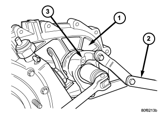
2. Use Spanner Wrench 6958 to secure the yoke (3) and remove the yoke nut. Discard nut after removal. It is not reusable.
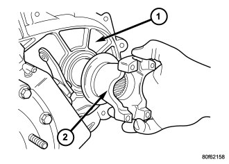
NOTE: The yoke is a taper fit onto the output shaft. It may be necessary to use a puller such as C-452 to remove the yoke.
3. Remove the yoke (2) from the front output shaft.
4. There is a seal slinger located on the rear of the yoke that can be replaced if necessary. Use a suitable cold chisel to strike the slinger hub parallel to the centerline in several spots to expand the slinger hub. A new slinger can be driven onto the yoke hub using a suitable pipe tool.
5. Remove yoke rubber seal from front output shaft.
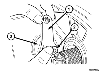
6. Remove bolt (2) that retains the shift lever (1) to sector shaft (3).
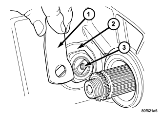
7. Remove the shift lever (1) from the shift sector (3).
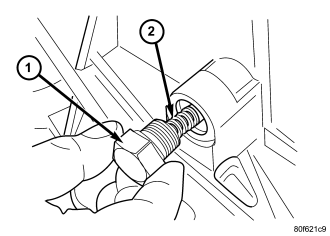
8. Remove the detente plug (1).
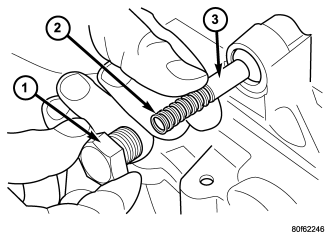
9. Remove the detente plug (1), spring (2), and plunger (3) from the transfer case.
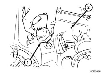
10. Remove the transfer case position sensor (1).
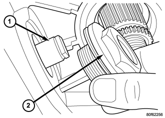
11. Remove the shift sector support (2).
MAINSHAFT, FRONT OUTPUT SHAFT, AND DRIVE CHAIN
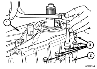
1. Note position of bolts that attach rear case (1) to front case (2). Some bolts are unique. Mark position of these bolts with paint or scribe.
2. Remove rear case-to-front case bolts (3).
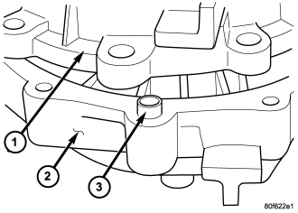
3. Loosen rear case (1) with pry tool to break sealer bead.
4. Unseat rear case from alignment dowels (3).
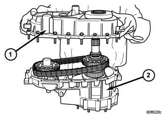
CAUTION: Do not remove the bolts holding the oil pump cover to the rear case half. The oil pump cover is aligned to the rear output shaft bearing inner race and will become mis-aligned if the bolts are loosened. If the transfer case failure has generated any debris which may have become trapped in the oil pump, the rear case and oil pump assembly MUST be replaced.
5. Remove rear case (1)and oil pump assembly from front case (2).
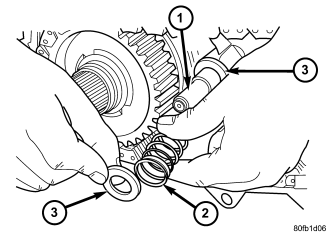
6. Remove shift rail cups (3) and spring (2).
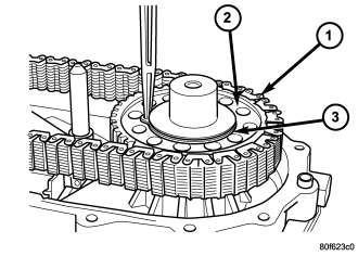
7. Remove front drive sprocket (2) retaining ring (3).
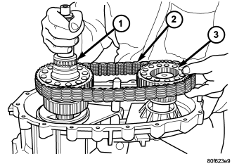
8. Remove mainshaft (1), front sprocket (3), and chain (2) as an assembly.
SHIFT FORKS
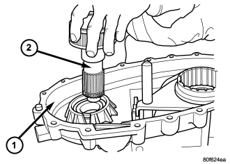
1. Remove front output shaft (2) from bearing in case (1).
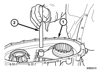
2. Remove the shift rail (2) from the shift forks.
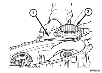
3. Remove mode fork (1), mode sleeve (2). Note which way sleeve fits in fork (long side of sleeve goes to front).
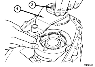
4. Remove range fork (1) and hub (2) as an assembly. Note fork position for installation reference.
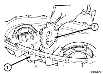
5. Remove shift sector (2).
MAINSHAFT
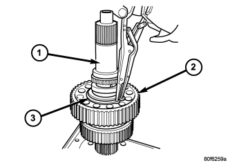
1. Remove the snap-ring (3) that secures the chain drive sprocket (2) onto mainshaft (1). Use standard (instead of parallel jaw) snap-ring pliers to remove this snap-ring.
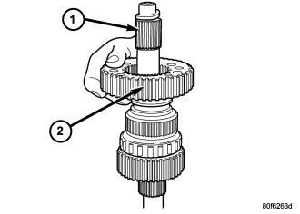
2. Remove drive sprocket (2).
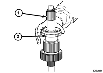
3. Remove the sliding clutch gear (2) from the mainshaft (1).
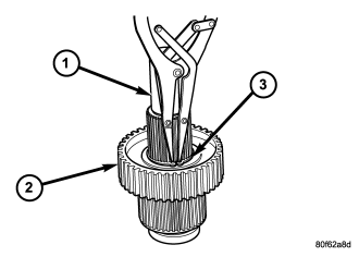
4. Rotate the mainshaft (1) 180° and remove the mode hub (2) snap-ring (3).
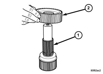
5. Remove the mode hub (2) from the mainshaft.
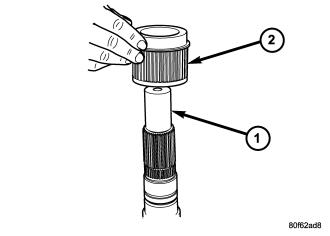
6. Remove the drive sprocket drive hub (2) from the mainshaft (1).
INPUT AND PLANETARY GEAR
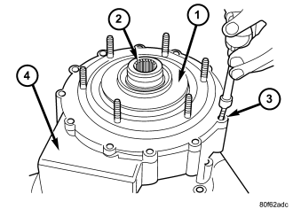
1. Remove front input retainer (1) attaching bolts (3).
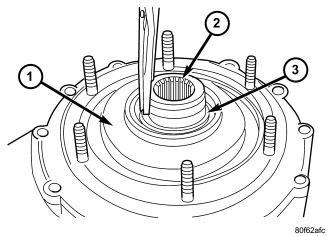
2. Remove the input gear (2) seal with a suitable screw and slide hammer.
3. Remove the input gear snap-ring (3) from the input retainer (1).
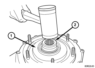
4. Remove the input gear (2) from the input gear bearing with suitable hammer.

5. Remove front input retainer (1).
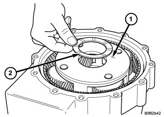
6. Remove the low range planetary (1) plastic spacer (2) from the planetary carrier or back side of the input retainer.
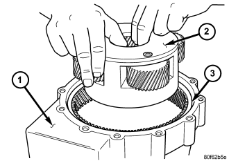
7. Remove the low range planetary gear set (2) from the front case half (1).
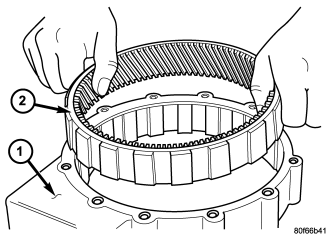
8. Remove the annulus gear (2) from the front case half (1).
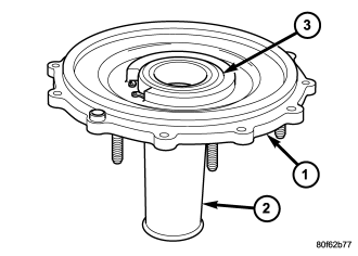
9. Support the input retainer (1) on Cup 8148 (2) as shown.
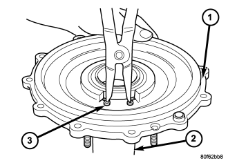
10. While using suitable snap-ring pliers to spread the input gear bearing snap-ring, press downward on the retainer (1) to remove the bearing (3).
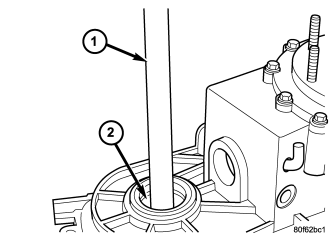
11. Remove the front output shaft bearing with Universal Handle C-4171 (1) and Installer 8239 (2).
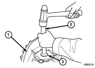
12. Remove the rear output shaft bearing with Universal Handle C-4171 (2) and Installer 8239 (3).
CLEANING
Clean the transfer case parts with a standard parts cleaning solvent. Remove all traces of sealer from the cases and retainers with a scraper and 3M™ all purpose cleaner. Use compressed air to remove solvent residue from oil feed passages in the case halves, retainers, gears, and shafts.
INSPECTION
MAINSHAFT/SPROCKET/HUB
Inspect the splines on the hub and shaft and the teeth on the sprocket. Minor nicks and scratches can be smoothed with an oilstone, however, replace any part that is damaged.
Check the contact surfaces in the sprocket bore and on the mainshaft. Minor nicks and scratches can be smoothed with 320-400 grit emery cloth but do not try to salvage the shaft if nicks or wear is severe.
INPUT GEAR AND PLANETARY CARRIER
Check the teeth on the gear. Minor nicks can be dressed off with an oilstone but replace the gear if any teeth are broken, cracked, or chipped. The bearing surface on the gear can be smoothed with 300-400 grit emery cloth if necessary.
Examine the carrier body and pinion gears for wear or damage. The carrier will have to be replaced as an assembly if the body, pinion pins, or pinion gears are damaged. Inspect the plastic washer on the inside, bottom of the planetary carrier. The washer is trapped by the pinion gears and the complete planetary will need to be replaced if the washer is worn or damaged.
SHIFT FORKS/HUBS/SLEEVES
Check condition of the shift forks and mode fork shift rail. Minor nicks on the shift rail can be smoothed with 320-400 grit emery cloth.
Inspect the shift fork wear pads. The mode and range fork pads are serviceable and can be replaced if necessary.
Check both of the sleeves for wear or damage, especially on the interior teeth. Replace the sleeves if wear or damage is evident.
DRIVE CHAIN
Examine the drive chain and shaft bearings. replace the chain if stretched, distorted, or if any of the links bind. Replace the bearings if rough, or noisy.
LOW RANGE ANNULUS GEAR
Inspect annulus gear condition carefully. The gear can be serviced separately.
FRONT-REAR CASES
Inspect the cases for wear and damage. Replace the input retainer seal, do not reuse it.
Check case condition. If leaks were a problem, look for gouges and severe scoring of case sealing surfaces. Also make sure the front case mounting studs are in good condition.
Check the front case mounting studs and vent tube. The tube can be secured with Loctite™ 271 or 680 if loose. The stud threads can be cleaned up with a die if necessary. Also check condition of the fill/drain plug threads in the rear case. The threads can be repaired with a thread chaser or tap if necessary. Or the threads can be repaired with Helicoil™ stainless steel inserts if required.
OIL PUMP/OIL PICKUP
Examine the oil pump pickup parts. Replace the pump if any evidence of debris or damage exists. Do not disassemble the pump from the rear case half as individual parts are not available and it will not be possible to reassemble the pump cover to the rear case half. The pump is only available as part of the rear case half assembly. The pickup screen, hose, and tube are the only serviceable parts and are available separately.
ASSEMBLY
BEARINGS AND SEALS
1. Position the input gear bearing in the input retainer bearing bore. Spread the snap-ring captured in the retainer with suitable snap-ring pliers and press the bearing into place. Verify that the snap-ring has engaged the groove in the bearing.
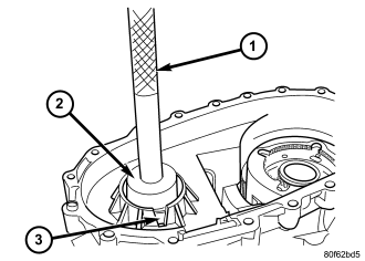
2. Start front output shaft bearing (3) in case. Then seat bearing with Universal Handle C-4171 (1) and Bearing Installer 6953 (2).
3. Install the front output shaft bearing retaining ring.
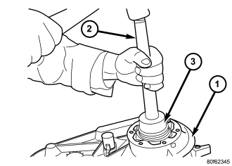
4. Install the rear output shaft bearing into the rear case half with Bearing Installer 6953 (3) and Universal Handle C-4171 (2).
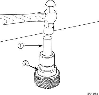
5. Remove the input gear pilot bearing using Remover Jaws 8240 and Cup 8148.
6. Remove the input gear cup plug with a suitable drift (1)and hammer inserted from the front of the input gear (2).
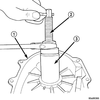
7. Install a new input gear cup plug with Cup Seal Installer 9045 and Universal Handle C-4171.
8. Install new input gear pilot bearing with Bearing Installer 9047 and Universal Handle C-4171.
9. Remove the front output shaft rear bearing with the screw and jaws from Remover L-4454 (2) and Cup 8148 (3).
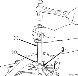
10. Install new bearing with Universal Handle C-4171 (1) and Bushing Installer 5066 (3).
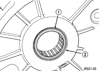
11. The bearing (1) bore is chamfered at the top. Install the bearing so it is flush with the lower edge of this chamfer (2).
INPUT AND PLANETARY GEAR
1. Install the annulus gear (2) into the front case half (1).
2. Align and install low range planetary (2) assembly into the front case half (1). Be sure low range planetary pinions are engaged in annulus gear (3).
3. Install the low range planetary plastic spacer (2) onto the low range planetary carrier (1).
4. Clean gasket sealer residue from retainer and inspect retainer for cracks or other damage.
5. Apply a 3 mm (1/8 in.) bead of MOPAR® Gasket Maker, or equivalent silicone adhesive, to sealing surface of retainer.
6. Install the front input retainer (1) onto the front case half (2).
7. Install bolts (3) to hold retainer (1) to transfer case (4). Tighten to 21 N·m (16 ft. lbs.) of torque.
8. Install the input gear (2) to the low range planetary assembly and the input gear bearing.
9. Install the input gear retaining snap-ring (3) onto the input gear (2).
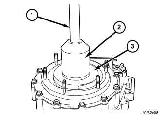
10. Install new oil seal in front input retainer with Seal Installer 8841 (2) and Universal Handle C-4171 (1).
SHIFT FORKS AND MAINSHAFT
1. Lubricate mainshaft splines with recommended transmission fluid.
2. Install the drive sprocket drive hub (2) onto the mainshaft (1). Verify that the long shoulder is towards the front of the mainshaft.
3. Install the mode hub (2) onto the mainshaft (1).
4. Install the mode hub snap-ring (3) onto the mainshaft (1).
5. Rotate the mainshaft (1) 180° and install the sliding clutch gear (2) onto the drive sprocket drive hub.
6. Install the mainshaft drive sprocket (2) onto the drive hub.
7. Install the mainshaft drive sprocket retaining ring (3) onto the drive hub.
8. Support front case on wood blocks so case interior is facing up. Place blocks between mounting studs on forward surface of case.
9. Lubricate mainshaft components with transmission fluid.
10. Lubricate sector shaft with transmission fluid and install shift sector (2) in case (1). Position slot in sector so it will be aligned with shift fork pin when shift forks are installed.
11. Assemble and install range fork (1) and hub (2). Be sure hub is properly seated in low range gear and engaged to the input gear.
12. Align and insert range fork pin in shift sector slot.
13. Install mode fork (1) and mode sleeve (2). Verify that the long side of the mode sleeve is towards the front of the transfer case.
14. Install the shift rail (2) through the shift forks and into the shift rail pocket in the front case half (1).
FRONT OUTPUT SHAFT AND DRIVE CHAIN
1. Install front output shaft (2) into the font output shaft bearing.
2. Install the front output shaft snap-ring onto the front output shaft.
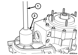
3. Install new front output seal in front case with Seal Installer 9041 (2) and Universal Handle C-4171 (1).
4. Insert front sprocket (3) in drive chain (2).
5. Install drive chain around mainshaft drive sprocket. Then position front sprocket over front output shaft.
6. Install the mainshaft (1) into the range hub and mode sleeve and seat the front drive sprocket onto the front output shaft.
7. Install the front drive sprocket retaining ring (3).
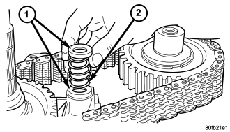
8. Install spring (2) and cups (1) on shift rail.
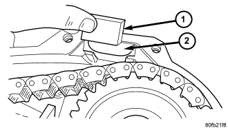
9. Insert magnet (1) in front case pocket (2).
OIL PUMP AND REAR CASE
CAUTION: Do not remove the bolts holding the oil pump cover to the rear case half. The oil pump cover is aligned to the rear output shaft inner bearing race and will become mis-aligned if the bolts are loosened. If the transfer case failure has generated any debris which may have become trapped in the oil pump. the rear case and oil pump assembly MUST be replaced.
Lubricate the oil pump components before installation. Prime the oil pickup tube by pouring a little oil into the tube before installation.
1. Install new o-ring in pickup tube inlet of oil pump.
2. Position oil pickup tube and filter in rear case. Be sure pickup filter is seated in case pocket and that pickup tube is aligned in case notches. Be sure hose that connects tube to filter is securely positioned.
3. Install the transfer case position sensor (1). Tighten the sensor to 20-34 N·m (16-25 ft.lbs.).
4. Install the shift sector support (2). Tighten the sector support to 27-42 N·m (20-30 ft.lbs.).
5. Install detente plunger (3) and spring (2) into the front case half.
6. Install new o-ring on detente plug (1) and install plug in front case. Tighten plug to 16-25 N·m (12-18 ft. lbs.).
7. Install shift lever (1) onto the shift sector (3).
8. Install the shift lever bolt (2). Tighten the bolt to 20-34 N·m (15-25 ft.lbs.)
9. Shift the transfer case into a 4WD range. This will raise the mainshaft slightly and make installation of the rear case half much easier.
10. Verify that the transfer case alignment dowels are properly installed.
11. Apply bead of MOPAR® Gasket Maker, or equivalent, to mating surface of front case. Keep sealer bead width to maximum of 3/16 inch. Do not use excessive amount of sealer as excess will be displaced into case interior.
12. Align oil pump with mainshaft and align shift rail with bore in rear case. Then install rear case (1) and oil pump assembly. Be sure oil pickup tube remains in position during case installation.
CAUTION: Verify that shift rail, and case alignment dowels (3) are seated before installing any bolts. Case could be cracked if shaft rail or dowels are misaligned.
13. Install 4-5 rear case-to front case bolts to hold rear case in position. Tighten bolts snug but not to specified torque at this time.
14. Apply Loctite™ 242 to remainder of rear case-to-front case bolt threads and install bolts (3). Tighten all bolts to 20-27 N·m (15-20 ft. lbs.).
YOKE
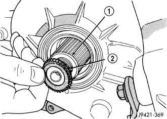
1. Install yoke seal (2) onto front shaft (1).
2. Install yoke (2) onto front shaft. Then install and tighten a new yoke nut to 122-176 N·m (90-130 ft. lbs.) torque. Never re-use a yoke nut.
REAR EXTENSION
1. Clean mating surfaces of transfer case housing and the rear retainer of any original gasket material.
2. Apply bead of Mopar® Gasket Maker, or equivalent, to mating surface of rear case. Keep sealer bead width to maximum of 3/16 inch. Do not use excessive amount of sealer as excess will be displaced into case interior.
3. Align and install rear extension on rear case.
4. Apply MOPAR® Silicone Sealer to threads of rear extension bolts. Then install extension bolts. Tighten the extension bolts to 16-25 N·m (12-18 ft.lbs.).
5. Install new seal in rear extension housing with Seal Installer 9041 and Universal Handle C-4171.
6. Install the rear companion flange (3) onto the output shaft.
7. Install bolts (4) into two threaded holes in the rear propeller shaft companion flange 180° apart.
8. Place the Holder 6719 (2) over the two bolts and use the Holder to install a new rear companion flange nut. Never re-use the companion flange nut once it has been installed. Tighten the companion flange nut to 122-176 N·m (90-130 ft.lbs.).
INSTALLATION
1. Align and seat transfer case on transmission. Be sure transfer case input gear splines are aligned with transmission output shaft. Align splines by rotating transfer case rear output shaft yoke if necessary. Do not install any transfer case attaching nuts until the transfer case is completely seated against the transmission.
2. Install and tighten transfer case attaching nuts. Tighten nuts to 30-41 N·m (20-30 ft.lbs.).
3. Install rear crossmember.
4. Remove jack stand from under transmission.
5. Align and connect propeller shafts. (Refer to 3 - DIFFERENTIAL & DRIVELINE/PROPELLER SHAFT/PROPELLER SHAFT - INSTALLATION)
6. Connect vacuum harness and vent hose.
7. Connect shift rod to transfer case lever or floor shift arm. Use channel lock style pliers to press rod back into lever grommet.
8. Adjust shift linkage, if necessary.
9. Fill transfer case with recommended transmission fluid and install fill plug.
10. Install skid plate, if equipped. (Refer to 13 - FRAMES & BUMPERS/FRAME/TRANSFER CASE SKID PLATE - INSTALLATION)
11. Lower vehicle