P0932-LINE PRESSURE SENSOR CIRCUIT
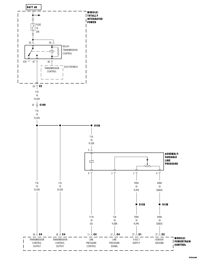
For a complete wiring diagram Refer to Section 8W.
Theory of Operation
Line pressure is electronically controlled by the Transmission Control System and is measured by the Line Pressure Sensor (LPS). The desired line pressure is continuously being compared to the actual line pressure and is regulated by electronically changing the duty cycle of the Pressure Control Solenoid (PCS). (5% duty cycle = solenoid off = max line pressure, 62% duty cycle = solenoid on = min line pressure).
The Transmission Control System calculates the desired line pressure based on inputs from the transmission and engine. A calculated torque input to the transmission is used as the primary input of the desired line pressure calculation and is called Torque Based Line Pressure. In addition, the line pressure is set to a preset level 827 to 931 kPa (120 to 135 psi) during shifts and in Park and Neutral to ensure consistent shift quality.
- When Monitored:
Continuously with the ignition on, engine running, with the transmission in gear.
- Set Condition:
The PCM continuously monitors Actual Line Pressure and compares it to Desired Line Pressure. If the Actual Line Pressure reading is more than 172.4 kPa (25 psi) higher than the Desired Line Pressure, but is less than the highest Line Pressure ever used in the current gear, the DTC sets.
| Possible Causes |
| RELATED DTC'S PRESENT |
| LINE PRESSURE CONNECTOR AND WIRING |
| INTERNAL TRANSMISSION |
| POWERTRAIN CONTROL MODULE |
Always perform the 42RLE Pre-Diagnostic Troubleshooting procedure before proceeding. (Refer to 21 - TRANSMISSION/TRANSAXLE/AUTOMATIC - 42RLE - STANDARD PROCEDURE)
Diagnostic Test
1. DETERMINING IF RELATED DTCS ARE PRESENTWith the scan tool, check for other transmission DTCs.
Are there any other line pressure related DTCs present?
Yes
- Refer to the Transmission category and perform the appropriate symptom. Perform the test for P0934 and/or P0935 first if present.
No
- Go To 2
2. COMPARE ACTUAL LINE PRESSURE TO DESIRED LINE PRESSURE
CAUTION: Apply Parking Brake
Start the engine.
CAUTION: Firmly apply the brakes.
With the scan tool, monitor the Line Pressure, Desired Line Pressure and the TPS degrees.
While firmly applying the brakes, place the shifter in Reverse, then slowly press the accelerator pedal to a TPS degree of 15°.
Compare the Line Pressure reading to the Desired Line Pressure reading on the scan tool.
Does the Line Pressure stay within ± 34 kPa or 5 psi of the Desired Line Pressure?
No
- Go To 3
Yes
- Go To 5
3. CHECK LINE PRESSURE CONNECTOR AND WIRING
Ignition on, engine not running.
With the scan tool, monitor the Line Pressure Sensor voltage while wiggling the wiring harness and connectors pertaining to the Line Pressure Sensor/Variable Force Solenoid Assembly.
Did the voltage remain steady while wiggling the wiring harness and connectors?
Yes
- Go To 4
No
- Disconnect and properly reconnect the Line Pressure Sensor/Variable Force Solenoid Assembly connector. Inspect terminals and repair as necessary.
- Perform 42RLE TRANSMISSION VERIFICATION TEST (Refer to 21 - TRANSMISSION/TRANSAXLE/AUTOMATIC - 42RLE - STANDARD PROCEDURE)
4. CHECK PCM AND WIRING
Turn the ignition off to the lock position.
Remove the Ignition Switch Feed fuse from the TIPM.
CAUTION: Removal of the Ignition Switch Feed fuse from the TIPM will prevent the vehicle from being started in gear.
WARNING: The Ignition Switch Feed fuse must be removed from the TIPM. Failure to do so can result in personal injury or death.
Install the Transmission Simulator, Miller tool #8333 and the Electronic Transmission Adapter kit.
With the Transmission Simulator select the "OFF" position on the "Input/Output Speed" switch.
Ignition on, engine not running.
With the scan tool, monitor the Line Pressure during the following step.
With the Transmission Simulator, turn the selector switch to each of the 3 Line Pressure positions.
NOTE: All three scan tool Line Pressure readings should be steady and ± 14 kPa or 2.0 psi of the reading specified on the Transmission Simulator.
Did the Line Pressure read within ± 14 kPa or 2.0 psi in all three positions?
Yes
- Using the schematics as a guide, check the Powertrain Control Module (PCM) terminals for corrosion, damage, or terminal push out. Pay particular attention to all power and ground circuits. If no problems are found, replace and program the PCM per the Service Information. With the scan tool, perform QUICK LEARN.
- Perform 42RLE TRANSMISSION VERIFICATION TEST (Refer to 21 - TRANSMISSION/TRANSAXLE/AUTOMATIC - 42RLE - STANDARD PROCEDURE)
No
- Repair internal transmission and inspect the oil pump per the Service information and replace if necessary. If no problems are found, replace the Line Pressure Sensor/Variable Force Solenoid Assembly — possible cause is the Pressure Control Solenoid is stuck.
- Perform 42RLE TRANSMISSION VERIFICATION TEST (Refer to 21 - TRANSMISSION/TRANSAXLE/AUTOMATIC - 42RLE - STANDARD PROCEDURE)
5. CHECK WIRING AND CONNECTORS
The conditions necessary to set this DTC are not present at this time.
Using the schematics as a guide, inspect the wiring and connectors specific to this circuit.
Wiggle the wires while checking for shorted and open circuits.
With the scan tool, check the DTC EVENT DATA to help identify the conditions in which the DTC was set.
Where there any problems found?
Yes
- Repair as necessary.
- Perform 42RLE TRANSMISSION VERIFICATION TEST (Refer to 21 - TRANSMISSION/TRANSAXLE/AUTOMATIC - 42RLE - STANDARD PROCEDURE)
No
- Test Complete.