Wheel Alignment
- DESCRIPTION
- OPERATION
- DIAGNOSIS AND TESTING - SUSPENSION AND STEERING SYSTEM
- HEIGHT MEASUREMENT
- CAMBER
- CASTER
- TOE POSITION
- SPECIFICATIONS
DESCRIPTION
DESCRIPTION
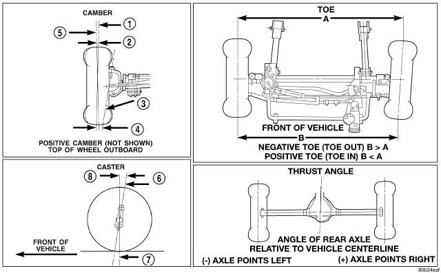 |
Wheel alignment involves the correct positioning of the wheels in relation to the vehicle. The positioning is accomplished through suspension and steering linkage adjustments. An alignment is considered essential for efficient steering, good directional stability and to minimize tire wear. The most important measurements of an alignment are caster, camber and toe position.
Never attempt to modify suspension
or steering components by heating or bending.
CAUTION:
| NOTE: |
Periodic lubrication of the front suspension/steering system components may be required. Rubber bushings must never be lubricated. Refer to Lubrication And Maintenance for the recommended maintenance schedule. |
OPERATION
OPERATION
- CASTER is the forward or rearward tilt of the steering knuckle from vertical. Tilting the top of the knuckle rearward provides positive caster. Tilting the top of the knuckle forward provides negative caster. Caster is a directional stability angle. This angle enables the front wheels to return to a straight ahead position after turns
- CAMBER is the inward or outward tilt of the wheel relative to the center of the vehicle. Tilting the top of the wheel inward provides negative camber. Tilting the top of the wheel outward provides positive camber. Incorrect camber will cause wear on the inside or outside edge of the tire. The angle is not adjustable, damaged component(s) must be replaced to correct the camber angle
- WHEEL TOE POSITION is the difference between the leading inside edges and trailing inside edges of the front tires. Incorrect wheel toe position is the most common cause of unstable steering and uneven tire wear. The wheel toe position is the final front wheel alignment adjustment
- STEERING AXIS INCLINATION ANGLE is measured in degrees and is the angle that the steering knuckles are tilted. The inclination angle has a fixed relationship with the camber angle. It will not change except when a spindle or ball stud is damaged or bent. The angle is not adjustable, damaged component(s) must be replaced to correct the steering axis inclination angle
- THRUST ANGLE is the angle of the rear axle relative to the centerline of the vehicle. Incorrect thrust angle can cause off-center steering and excessive tire wear. This angle is not adjustable, damaged component(s) must be replaced to correct the thrust angle
DIAGNOSIS AND TESTING - SUSPENSION AND STEERING SYSTEM
DIAGNOSIS AND TESTING - SUSPENSION AND STEERING SYSTEM
|
CONDITION |
POSSIBLE CAUSES |
CORRECTION |
|---|---|---|
|
FRONT END NOISE |
1. Loose or worn wheel bearings. |
1. Adjust or replace wheel bearings. |
|
2. Loose or worn steering or suspension components. |
2. Tighten or replace components as necessary. |
|
|
EXCESSIVE PLAY IN STEERING |
1. Loose or worn wheel bearings. |
1. Adjust or replace wheel bearings. |
|
2. Loose or worn steering or suspension components. |
2. Tighten or replace components as necessary. |
|
|
3. Loose or worn steering gear. |
3. Adjust or replace steering gear. |
|
|
FRONT WHEELS SHIMMY |
1. Loose or worn wheel bearings. |
1. Adjust or replace wheel bearings. |
|
2. Loose or worn steering or suspension components. |
2. Tighten or replace components as necessary. |
|
|
3. Tires worn or out of balance. |
3. Replace or balance tires. |
|
|
4. Alignment. |
4. Align vehicle to specifications. |
|
|
5. Leaking steering damper. |
5. Replace steering damper. |
|
|
6. Tire pressure. |
6. Adjust tire pressure. |
|
|
VEHICLE INSTABILITY |
1. Loose or worn wheel bearings. |
1. Adjust or replace wheel bearings. |
|
2. Loose or worn steering or suspension components. |
2. Tighten or replace components as necessary. |
|
|
3. Tire pressure. |
3. Adjust tire pressure. |
|
|
4. Alignment. |
4. Align vehicle to specifications. |
|
|
EXCESSIVE STEERING EFFORT |
1. Loose or worn steering gear. |
1. Adjust or replace steering gear. |
|
2. Power steering fluid low. |
2. Add fluid and repair leak. |
|
|
3. Column coupler binding. |
3. Replace coupler. |
|
|
4. Tire pressure. |
4. Adjust tire pressure. |
|
|
5. Alignment. |
5. Align vehicle to specifications. |
|
|
VEHICLE PULLS TO ONE SIDE DURING BRAKING |
1. Uneven tire pressure. |
1. Adjust tire pressure. |
|
2. Worn brake components. |
2. Repair brakes as necessary. |
|
|
3. Air in brake line. |
3. Repair as necessary. |
|
|
VEHICLE LEADS OR DRIFTS FROM STRAIGHT AHEAD DIRECTION ON UNCROWNED ROAD |
1. Radial tire lead. |
1. Cross front tires. |
|
2. Brakes dragging. |
2. Repair brake as necessary. |
|
|
3. Weak or broken spring. |
3. Replace spring. |
|
|
4. Uneven tire pressure. |
4. Adjust tire pressure. |
|
|
5. Wheel Alignment. |
5. Align vehicle. |
|
|
6. Loose or worn steering or suspension components. |
6. Repair as necessary. |
|
|
7. Cross caster out of spec. |
7. Align vehicle. |
|
|
KNOCKING, RATTLING OR SQUEAKING |
1. Worn shock bushings. |
1. Replace shock. |
|
2. Loose, worn or bent steering/suspension components. |
2. Inspect, tighten or replace components as necessary. |
|
|
3. Shock valve. |
3. Replace shock. |
|
|
IMPROPER TRACKING |
1. Loose, worn or bent track bar. |
1. Inspect, tighten or replace component as necessary. |
|
2. Loose, worn or bent steering/suspension components. |
2. Inspect, tighten or replace components as necessary. |
HEIGHT MEASUREMENT
HEIGHT MEASUREMENT
FRONT CURB HEIGHT
| NOTE: |
The suspension is non-adjustable. |
The vehicle suspension height should be measured before performing wheel alignment procedure. Also when front suspension components have been replaced. This measure must be performed with the vehicle supporting it's own weight and taken on both sides of the vehicle.
Front and rear curb heights are not adjustable. The spring selections at assembly determine curb height for acceptable appearance of the vehicle. Curb height dimensions assume full fluids (including fuel) and zero passengers. Refer to the table below for front curb height dimensions.
Vehicle curb height audits should be performed utilizing the following procedure:
| NOTE: |
Make sure the vehicle is in 2WD when checking curb height. |
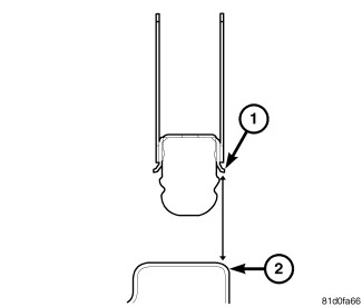 |
Front – On each side of the vehicle, measure the distance from the bottom of the jounce bumper cup (1) to the top lip of the inner spring seat on axle (2).
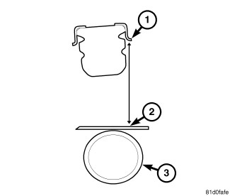 |
REAR CURB HEIGHTRear – On each side of the vehicle, measure the distance from the bottom of the jounce bumper cup (1) to the top (2) of the rear axle (3).
CURB HEIGHT SPECIFICATIONS
|
MODEL |
FRONT |
REAR |
|---|---|---|
|
4X2 |
63 mm / +25 mm to -12 mm |
102 mm / +25 mm to -12 mm |
|
2.48 in. / + 0.98 to -0.47 in |
4.01 in /. + 0.98 to -0.47 in |
|
|
4X4 Short Wheel Base (SWB) X / SPORT / SAHARA |
93 mm / +25 mm to -12 mm |
126 mm / +25 mm to -12 mm |
|
3.66 in. / + 0.98 to -0.47 in |
4.96 in. / + 0.98 to -0.47 in |
|
|
4X4 Short Wheel Base (SWB) RUBICON |
97 mm / +25 mm to -12 mm |
130 mm / +25 mm to -12 mm |
|
3.81 in. / + 0.98 to -0.47 in |
5.11 in. / + 0.98 to -0.47 in |
|
|
4X4 Short Wheel Base (SWB) DIESEL - ALL |
76 mm / +25 mm to -12 mm |
126 mm / +25 mm to -12 mm |
|
2.99 in. / + 0.98 to -0.47 in |
4.96 in. / + 0.98 to -0.47 in |
|
|
4X4 Long Wheel Base (LWB) X / SPORT / SAHARA |
93 mm / +25 mm to -12 mm |
132 mm / +25 mm to -12 mm |
|
3.66 in. / + 0.98 to -0.47 in |
5.19 in./ + 0.98 to -0.47 in |
|
|
4X4 Long Wheel Base (LWB) RUBICON |
97 mm / +25 mm to -12 mm |
136 mm / +25 mm to -12 mm |
|
3.81 in. / + 0.98 to -0.47 in |
5.35 in. / + 0.98 to -0.47 in |
|
|
4X4 Long Wheel Base (LWB) DIESEL - ALL |
76 mm / +25 mm to -12 mm |
132 mm / +25 mm to -12 mm |
|
2.99 in. / + 0.98 to -0.47 in |
5.19 in. / + 0.98 to -0.47 in |
TOLERANCES
|
INDIVIDUAL |
CROSS CAR |
|---|---|
|
+25 mm -12 mm (0.984 in. - 0.47 in) |
± 12 mm (± 0.47 in) |
CAMBER
CAMBER
Before each alignment reading the vehicle should be jounced (rear first, then front). Grasp each bumper at the center and jounce the vehicle up and down three times. Always release the bumper in the down position.
The wheel camber angle is preset. This angle is not adjustable and cannot be altered.
CASTER
CASTER
Before each alignment reading the vehicle should be jounced (rear first, then front). Grasp each bumper at the center and jounce the vehicle up and down three times. Always release the bumper in the down position.
Check the caster of the front axle for correct angle. Be sure the axle is not bent or twisted. Road test the vehicle and observe the steering wheel return-to-center position. Low caster will cause poor steering wheel return ability.
During the road test, turn the vehicle to both the left and right. If the steering wheel returns to the center position unassisted, the caster angle is correct. However, if steering wheel does not return toward the center position unassisted, a low caster angle is probable.
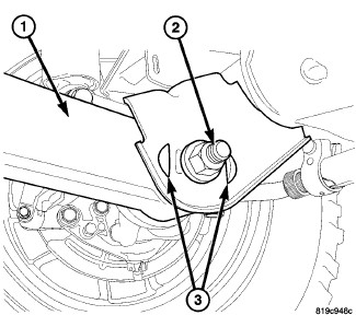 |
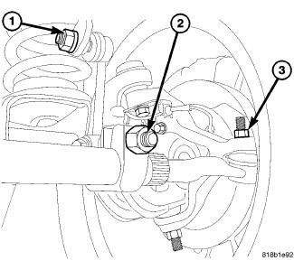
Caster can be adjusted by installing a Mopar® cam adjustment kit located between the notches in the axle bracket (3) and moving the lower suspension arm (1) at the axle forward or rearward.
The lower suspension arm will have to be removed at the axle bracket and then the knock-outs will have to be removed in order for the kit to be installed. (Refer to 02 - Front Suspension/Front/ARM, Lower Control - Removal) .
| NOTE: |
Changing caster angle will also change the front propeller shaft angle. The propeller shaft angle has priority over caster. Refer to Group 3, Differential and Driveline for additional information. |
TOE POSITION
TOE POSITION
Before each alignment reading the vehicle should be jounced (rear first, then front). Grasp each bumper at the center and jounce the vehicle up and down three times. Always release the bumper in the down position.
 |
| NOTE: |
The wheel toe position adjustment is the final adjustment. This adjustment must be performed with the engine running, if the vehicle is equipped with power steering. |
- Start the engine and turn wheels both ways before straightening the steering wheel. Center and secure the steering wheel.
- Loosen the adjustment sleeve clamp bolts (2).
-
Adjust the total toe with the tie rod. Turn the knurled adjuster until the correct total toe is reached. Center both sockets at the knuckles and tighten the clamp bolts to 61 N·m (45 ft.lbs). Make sure the toe setting does not change during clamp tightening.
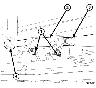
- Adjust the drag link adjuster sleeve so that the left and right toe values are equal. Verify the steering wheel is still straight. Position the clamps as shown and tighten to 35 N·m (26 ft. lbs.).
-
Verify the toe specifications and turn off the engine.
SPECIFICATIONS
SPECIFICATIONS
| NOTE: |
Alignment specifications are in degrees. |
FRONT
|
FRONT WHEEL ALIGNMENT |
PREFERRED SETTING |
ACCEPTABLE RANGE |
|---|---|---|
|
CAMBER |
-0.25° (fixed angle) |
-0.62° to +0.12° |
|
Cross Camber (Maximum Side-To-Side Difference) |
± 0.5° |
± 0.5° |
|
CASTER (left side) |
+4.2° |
+3.2° to +5.2° |
|
CASTER - (right side) |
+4.4° |
+3.4° to +5.4° |
|
Cross Caster (Maximum Side-To-Side Difference) |
-0.2° |
-0.7° to +0.3° |
|
TOE - TOTAL* |
+0.20° |
+0.17° to +0.23° |
|
Positive toe (+) is toe-in and negative toe (−) is Toe-out. |
|
* TOTAL TOE is the sum of both the left and right wheel toe settings. TOTAL TOE should be equally split between each wheel on the same axle to ensure the steering wheel is centered after setting toe. |
REAR
|
REAR WHEEL ALIGNMENT |
PREFERRED SETTING |
ACCEPTABLE RANGE |
|---|---|---|
|
CAMBER |
-0.25° |
+0.0° to -50° |
|
TOE - TOTAL* |
+0.25° |
+0.0° to +0.50° |
|
THRUST ANGLE |
0.00° |
-0.25° to +0.25° |
|
Positive toe (+) is toe-in and negative toe (−) is Toe-out. |
|
* TOTAL TOE is the sum of both the left and right wheel toe settings. TOTAL TOE should be equally split between each wheel on the same axle to ensure the steering wheel is centered after setting toe. |