B1030-11-EVAPORATOR TEMPERATURE SENSOR - CIRCUIT SHORT TO GROUND
B1030-11-EVAPORATOR TEMPERATURE SENSOR - CIRCUIT SHORT TO GROUND
 |
For a complete wiring diagram, refer to the Wiring Information.
Theory of Operation
The HVAC A/C heater control uses a variety of sensors to adjust HVAC operation to obtain optimal performance. These sensors are continuously monitored by the A/C heater control to assure that they are in range. An active Diagnostic Trouble Code (DTC) indicates that a sensor is out of range. A stored DTC indicates that the sensor was out of range but is currently within range.
The evaporator temperature sensor monitors the surface temperature of the A/C evaporator and supplies an input signal to the A/C heater control. The input signal value is used to optimize the A/C system performance and to protect the A/C evaporator from freezing. The evaporator temperature sensor resistance value will change in response to the surface temperature of A/C evaporator. The resistance value is electronically transferred to the A/C heater control using a sensor ground circuit and a 5-volt reference signal circuit. Normal operation of the sensor the resistive value decreases when the A/C evaporator temperature decreases and the sensor resistive value increases when A/C evaporator temperature increases.
-
When Monitored:
With the ignition on.
-
Set Condition:
The Evaporator Temperature Sensor voltage input to the A/C Heater Control is equal to or below 0.9 of a volt for a continuous period of 1.2 seconds. If the A/C Heater Control detects a valid voltage, the Diagnostic Trouble Code (DTC) will change from active to stored and will stay stored for 100 ignition cycles.
Possible Causes |
|---|
| (C21) EVAPORATOR TEMPERATURE SENSOR SIGNAL CIRCUIT SHORTED TO GROUND |
| EVAPORATOR TEMPERATURE SENSOR |
| A/C HEATER CONTROL |
Always perform the HVAC Pre-Diagnostic Troubleshooting procedure before proceeding. (Refer to 28 - DTC-Based Diagnostics/HVAC - Standard Procedure) .
| 1. | Ignition on, engine not running. |
| 2. | Using the scan tool, read HVAC DTCs. |
Is this DTC active?
Yes
- Go To 2
No
- Go To 5
2. CHECK (C21) EVAPORATOR TEMPERATURE SENSOR SIGNAL CIRCUIT FOR A SHORT TO GROUND
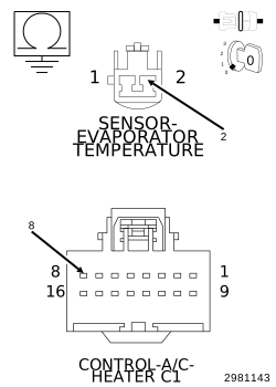 |
| 1. | Turn the ignition off to the lock position. |
| 2. | Disconnect the A/C Heater Control C1 harness connector. |
| 3. | Disconnect the Evaporator Temperature Sensor harness connector. |
| 4. | Measure the resistance between ground and the (C21) Evaporator Temperature Sensor Signal circuit. |
Is the resistance below 100k Ohms?
Yes
- Repair the (C21) Evaporator Temperature Sensor Signal circuit for a short to ground.
- Perform the HVAC VERIFICATION TEST. (Refer to 28 - DTC-Based Diagnostics/HVAC - Standard Procedure) .
No
-
Go To 3
3. CHECK (C21) EVAPORATOR TEMPERATURE SENSOR SIGNAL CIRCUIT FOR A SHORT TO THE (C121) SENSOR GROUND CIRCUIT
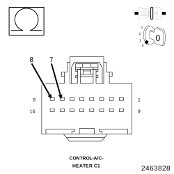 |
| 1. | Measure the resistance between the (C21) Evaporator Temperature Sensor Signal circuit and the (C121) Sensor Ground circuit. |
Is the resistance below 100k Ohms?
Yes
- Repair the (C21) Evaporator Temperature Sensor Signal circuit for a short to (C121) Sensor Ground circuit.
- Perform the HVAC VERIFICATION TEST. (Refer to 28 - DTC-Based Diagnostics/HVAC - Standard Procedure) .
No
-
Go To 4
4. CHECK THE EVAPORATOR TEMPERATURE SENSOR
| 1. | Replace the Evaporator Temperature Sensor in accordance with the Service Information. (Refer to 24 - Heating and Air Conditioning/Controls/SENSOR, Evaporator Temperature - Removal) . |
| 2. | Cycle the ignition off for 30 seconds then back on. |
| 3. | With the scan tool, read HVAC DTCs. |
Does this DTC reset?
Yes
- Replace and program the A/C Heater Control in accordance with the Service Information. (Refer to 24 - Heating and Air Conditioning/Controls/CONTROL, A/C and Heater - Removal) .
- Perform the HVAC VERIFICATION TEST. (Refer to 28 - DTC-Based Diagnostics/HVAC - Standard Procedure) .
No
- Test complete.
- Perform the HVAC VERIFICATION TEST. (Refer to 28 - DTC-Based Diagnostics/HVAC - Standard Procedure) .
5. CHECK THE WIRING AND CONNECTORS
| 1. | The conditions necessary to set the DTC are not present at this time. |
| 2. | Using the scan tool, check the Environmental Data to help identify the conditions in which the DTC was set. |
| 3. | Using the wiring diagrams as a guide, check all related splices and connectors for signs of water intrusion, corrosion, pushed out or bent terminals, and correct pin tension. |
| 4. | Wiggle the wiring and connectors while checking for shorted and open circuits. |
Were there any problems found?
Yes
- Repair as necessary.
- Perform the HVAC VERIFICATION TEST. (Refer to 28 - DTC-Based Diagnostics/HVAC - Standard Procedure) .
No