P0161-O2 SENSOR 2/2 HEATER PERFORMANCE
P0161-O2 SENSOR 2/2 HEATER PERFORMANCE
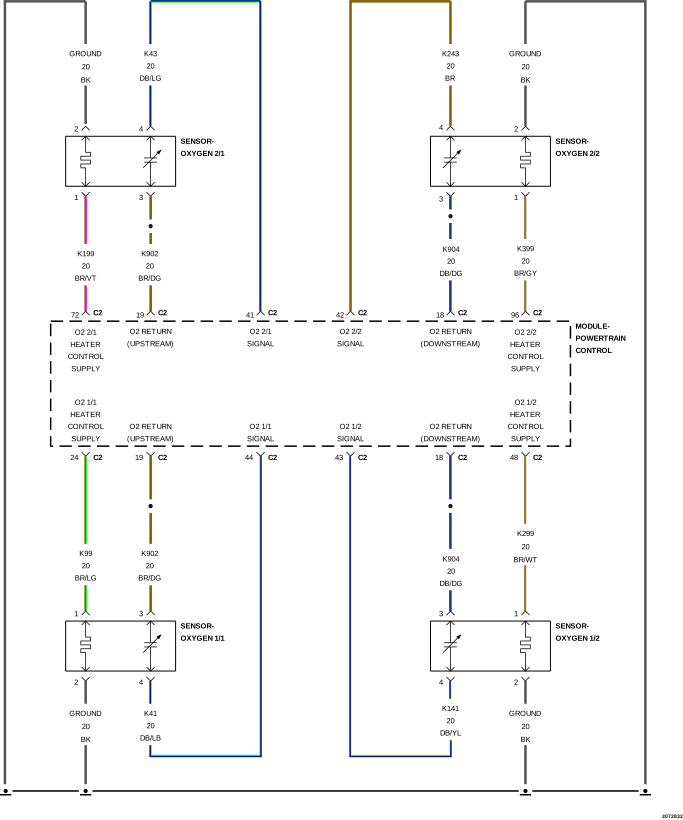 |
For a complete wiring diagram, refer to the Wiring Information.
Theory of Operation
This diagnostic provides a continuous check of the O2 Sensor Heater circuit during operation. The heater circuit is momentarily disabled to allow a resistance measurement to be taken to infer heater temperature. The current delivery to the heater is duty cycled to maintain a specific target temperature. The error from the target temperature is continuously monitored to assess heater performance.
-
When Monitored:
Engine running and heater duty cycle greater than 0%. Battery voltage greater than 11.0 Volts.
-
Set Condition:
No sensor output is received when the PCM powers up the O2 Sensor Heater. Two trip fault. Three good trips to turn off the MIL.
Possible Causes |
|---|
| (K399) O2 SENSOR 2/2 HEATER CONTROL CIRCUIT OPEN |
| O2 SENSOR 2/2 HEATER GROUND CIRCUIT OPEN |
| O2 SENSOR 2/2 |
| POWERTRAIN CONTROL MODULE (PCM) |
Always perform the Pre-Diagnostic Troubleshooting procedure before proceeding. (Refer to 28 - DTC-Based Diagnostics/MODULE, Powertrain Control (PCM) - Standard Procedure).
| 1. | Turn the ignition off. |
| NOTE: | Wait a minimum of eight minutes to allow the O2 Sensor to cool down before continuing the test. Allow the O2 Sensor voltage to stabilize between 4.6 and 5.0 Volts. |
| 2. | Ignition on, engine not running. |
| 3. | With the scan tool, actuate the O2 Heater Test. |
| 4. | With the scan tool, monitor O2 Sensor 2/2 voltage for at least two minutes. |
Does the voltage stay above 4.5 Volts?
Yes
- Go To 2
No
- Perform the INTERMITTENT CONDITION diagnostic procedure. (Refer to 28 - DTC-Based Diagnostics/MODULE, Powertrain Control (PCM) - Standard Procedure).
2. O2 SENSOR 2/2 HEATER ELEMENT
| 1. | Turn the ignition off. |
| NOTE: | Allow the O2 sensor to cool down to room temperature. |
| 2. | Disconnect the O2 Sensor 2/2 harness connector. |
| 3. | Measure the resistance of the O2 Sensor Heater Element across the O2 Sensor, between the O2 Heater Control terminal and the O2 Heater ground terminal. |
| NOTE: | O2 Sensor 2/2 Heater Element resistance values should be measured at 21.1°C (70°F). The resistance value will vary with different temperature values. |
Is the resistance of the O2 Sensor 2/2 Heater Element between 2.0 and 30.0 Ohms?
Yes
- Go To 3
No
- Verify that there is good pin to terminal contact in the O2 Sensor 2/2 and Powertrain Control Module connectors. If OK, replace the O2 Sensor 2/2. (Refer to 14 - Fuel System/Fuel Injection/SENSOR, Oxygen - Removal) .
- Perform the POWERTRAIN VERIFICATION TEST. (Refer to 28 - DTC-Based Diagnostics/MODULE, Powertrain Control (PCM) - Standard Procedure).
3. (K399) O2 SENSOR 2/2 HEATER CONTROL CIRCUIT OPEN
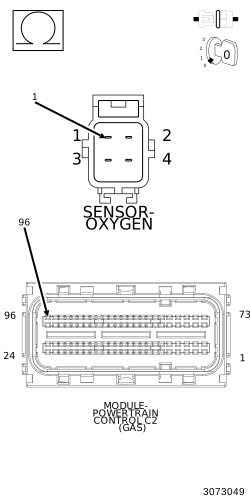 |
| 1. | Disconnect the PCM C2 harness connector. |
| 2. | Measure the resistance of the (K399) O2 Sensor 2/2 Heater Control circuit from the O2 Sensor 2/2 connector to the PCM C2 harness connector. |
Is the resistance below 0.5 Ohm?
Yes
- Go To 4
No
- Repair the excessive resistance in the (K399) O2 Sensor 2/2 Heater Control circuit.
-
Perform the POWERTRAIN VERIFICATION TEST. (Refer to 28 - DTC-Based Diagnostics/MODULE, Powertrain Control (PCM)
- Standard Procedure).
4. O2 SENSOR 2/2 HEATER GROUND CIRCUIT OPEN
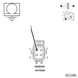 |
| 1. | Measure the resistance between ground and the O2 Sensor 2/2 Heater ground circuit in the O2 Sensor 2/2 harness connector. |
Is the resistance below 0.5 Ohm?
Yes
- Go To 5
No
- Repair the excessive resistance in the O2 Sensor 2/2 Heater ground circuit.
-
Perform the POWERTRAIN VERIFICATION TEST. (Refer to 28 - DTC-Based Diagnostics/MODULE, Powertrain Control (PCM)
- Standard Procedure).
5. POWERTRAIN CONTROL MODULE (PCM)
| 1. | Using the wiring diagram/schematic as a guide, inspect the wiring and connectors between the Oxygen Sensor 2/2 and the Powertrain Control Module (PCM). |
| 2. | Look for any chafed, pierced, pinched or partially broken wires. |
| 3. | Look for broken, bent, pushed out or corroded terminals. Verify that there is good pin to terminal contact in the Oxygen Sensor 2/2 and Powertrain Control Module connectors. |
| 4. | Perform any Technical Service Bulletins that may apply. |
Were there any problems found?
Yes
- Repair as necessary.
- Perform the POWERTRAIN VERIFICATION TEST. (Refer to 28 - DTC-Based Diagnostics/MODULE, Powertrain Control (PCM) - Standard Procedure).
No
- Replace and program the Powertrain Control Module in accordance with the Service Information. (Refer to 08 - Electrical/8E - Electronic Control Modules/MODULE, Powertrain Control - Removal) .
- Perform the POWERTRAIN VERIFICATION TEST. (Refer to 28 - DTC-Based Diagnostics/MODULE, Powertrain Control (PCM) - Standard Procedure).